Shell press and method for forming a shell

a technology of container end panels and shells, which is applied in the direction of manufacturing tools, shaping tools, other domestic objects, etc., can solve the problems of excessive heating of the inner pressure sleeve in the shell forming process, unsatisfactory excess heat generation of the inner pressure sleeve, etc., to avoid excessive heat generation and avoid excessive strain hardening of the chuck wall

a technology of container end panels and shells, which is applied in the direction of manufacturing tools, shaping tools, other domestic objects, etc., can solve the problems of excessive heating of the inner pressure sleeve in the shell forming process, unsatisfactory excess heat generation of the inner pressure sleeve, etc., to avoid excessive heat generation and avoid excessive strain hardening of the chuck wall

US20070283738A1Active Publication Date: 2007-12-13STOLLE MACHINERY

Image

  • Shell press and method for forming a shell
  • Shell press and method for forming a shell
  • Shell press and method for forming a shell

Examples


Embodiment Construction

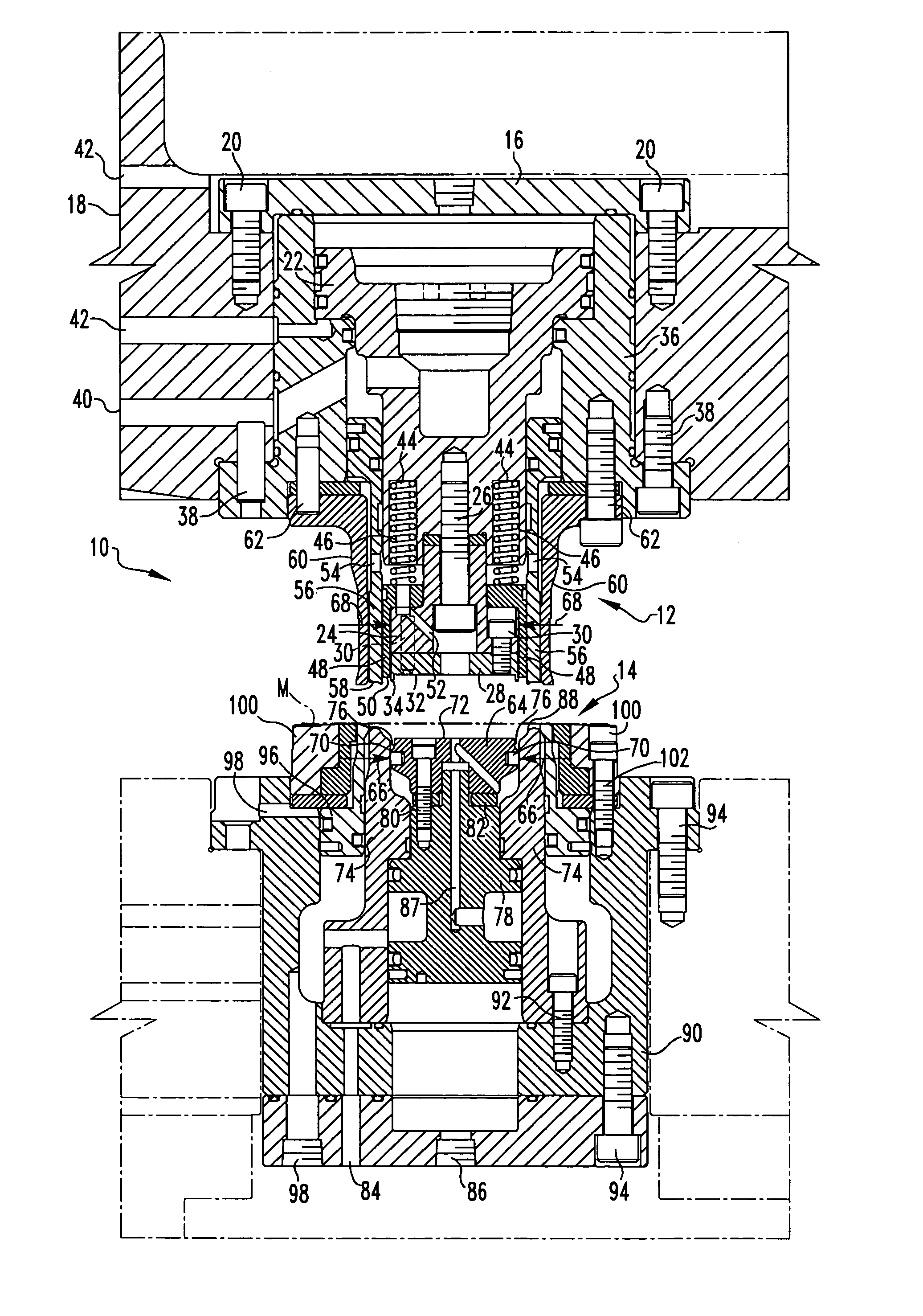
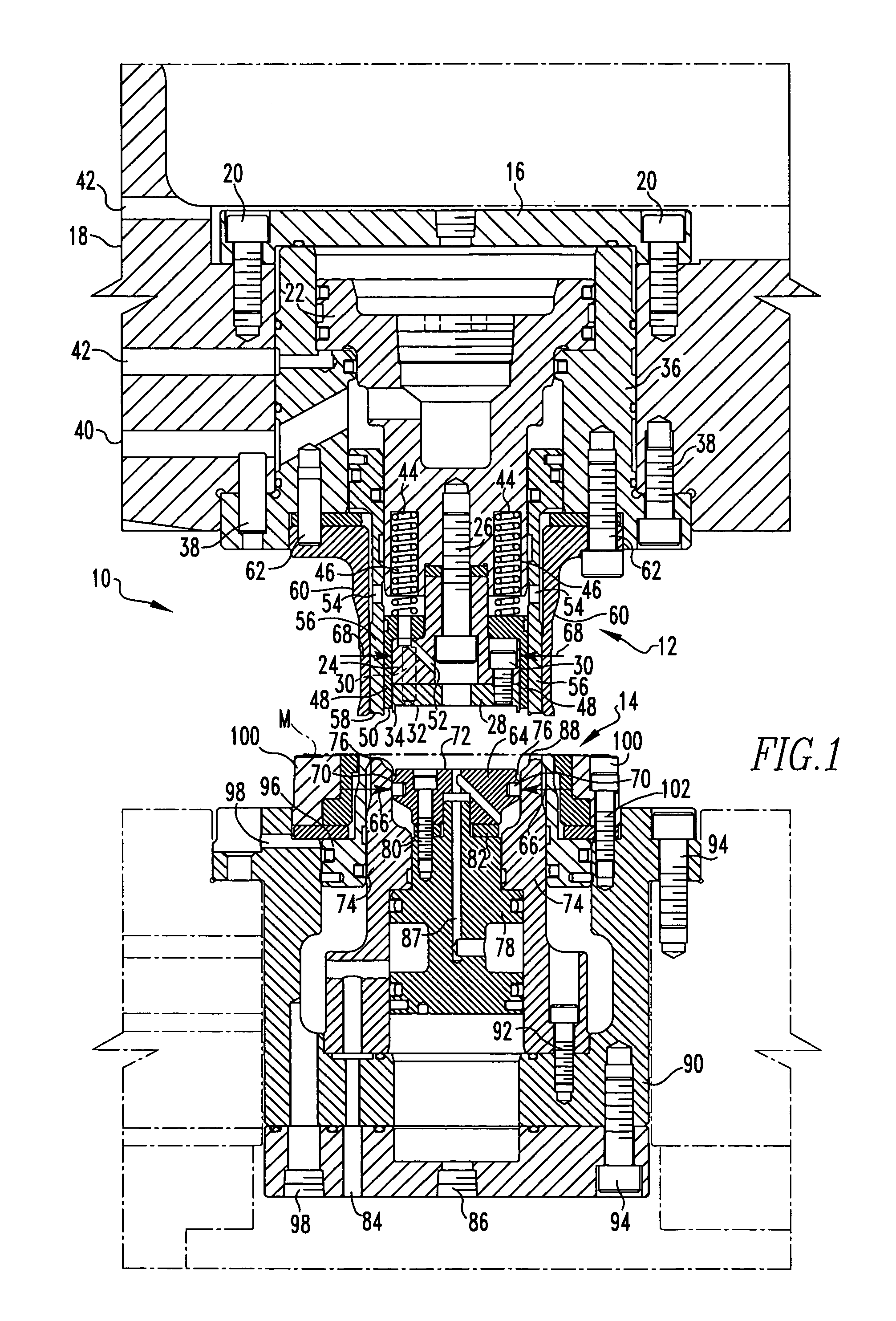
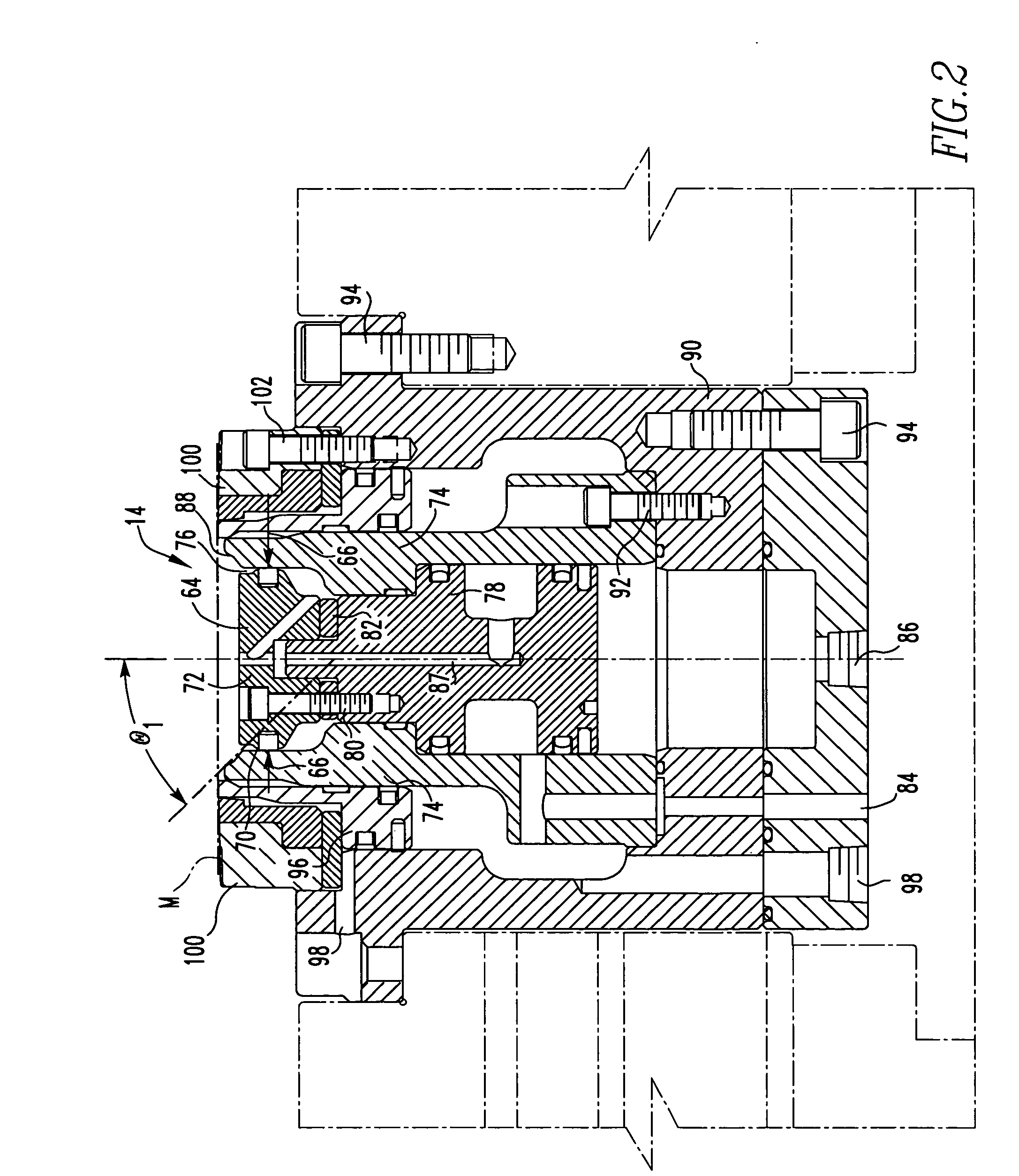
[0024] For purposes of the description hereinafter, the terms “upper”, “lower”, “vertical”, “horizontal”, “top”, “bottom”, “aft”, “behind”, and derivatives thereof shall relate to the invention, as it is oriented in the drawing FIGS. However, it is to be understood that the invention may assume various alternative configurations except where expressly specified to the contrary. It is also to be understood that the specific elements illustrated in the FIGS. and described in the following specification are simply exemplary embodiments of the invention. Therefore, specific dimensions, orientations and other physical characteristics related to the embodiments disclosed herein are not to be considered limiting.

[0025] As employed herein, the term “fastener” refers to any suitable fastening, connecting or tightening mechanism by way of example and not limitation, dowel pins, fasteners, rivets and the like. As employed herein, the statement that two or more parts are “coupled” together sha...


PUM

PropertyMeasurementUnit
angleaaaaaaaaaa
angleaaaaaaaaaa
internal pressuresaaaaaaaaaa

Abstract

An apparatus and method for forming a shell with a central panel and a chuck wall is provided. The apparatus and method employ the use of a biasing member to selectively bias and control movement of the inner pressure sleeve and a die core having an outer diameter equal to or greater than the outer diameter of the punch core. The apparatus and method can also be employed in a single action press or a double action press.

Description

FIELD OF THE INVENTION [0001] The invention generally relates to an apparatus and method for forming container end panels, commonly called shells, from a sheet of blanked material. More particularly, the invention relates to a press and method for forming the shell with the press having a biasing member that selectively biases and controls movement of the inner pressure sleeve and a die core having an outer diameter equal to or greater than the outer diameter of the punch core. BACKGROUND OF THE INVENTION [0002] The forming of can ends or shells for can bodies, namely aluminum or steel cans, is well-known in the art. Shells typically have a central panel connected to an inner panel wall which is connected to a countersink. The countersink is usually connected to a chuck wall of the shell which is connected to a peripheral curl that is structured to be seamed onto a can body. [0003] A representative patent disclosing shell forming is Bulso U.S. Pat. No. 4,716,755. As is typically see...

Claims


Application Information

Patent Timeline
13 Dec 2007
Publication
US20070283738A1
IPC
B21D22/21
CPC
B21D51/38
Inventors
TURNBULL, ROBERT DEAN; STEFANSIC, DONNA REBECCA