Radio receiving apparatus and method

a technology of receiving apparatus and receiving characteristic, applied in the direction of transmission monitoring, pulse technique, polarisation/directional diversity, etc., can solve the problems of affecting the quality of input signals, so as to achieve high receiving characteristic

Inactive Publication Date: 2007-12-11
KK TOSHIBA
View PDF9 Cites 11 Cited by
  • Summary
  • Abstract
  • Description
  • Claims
  • Application Information

AI Technical Summary

Benefits of technology

[0010]The present invention has been developed in light of the above-described technique, and aims to provide a radio receiving apparatus that exhibits a high receiving characteristic when a single control signal is used to control signals received by a plurality of antennas, and a radio receiving method employed in the apparatus.

Problems solved by technology

If an analog signal cannot appropriately be converted into a digital signal since its power exceeds the range, the resultant digital signal is distorted.
It is well known that this distortion significantly degrades the receiving characteristic.
However, if a plurality of gain adjusting devices must be controlled by a single control signal, it is difficult to appropriately control all input signals since the input signals may be adjusted using different gain-adjusting values.
However, if the amplitudes of analog signals received by the antenna elements are reduced, as in the publication, to values that enable the A / D converters to appropriately convert the analog signals into digital signals, the receiving characteristic of a synthetic signal obtained by synthesizing a plurality of digital signals corresponding to the analog signals may degrade.

Method used


Image

  • Radio receiving apparatus and method
  • Radio receiving apparatus and method
  • Radio receiving apparatus and method

Examples


Embodiment Construction

[0027]A radio receiving apparatus and method according to an embodiment of the invention will be described in detail with reference to the accompanying drawings.

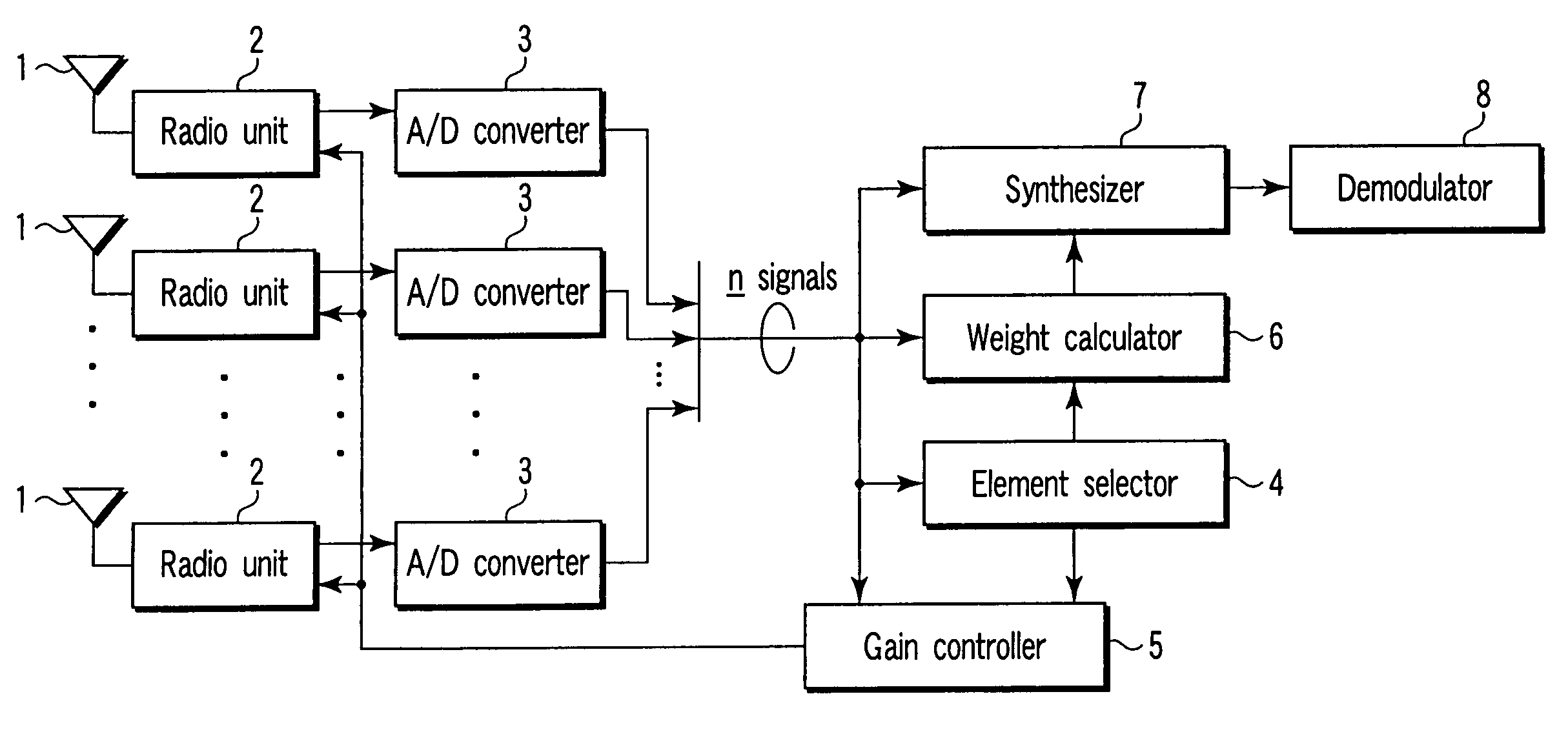
[0028]Referring first to FIG. 1, a structure example of the radio receiving apparatus of the embodiment will be described. FIG. 1 is a block diagram illustrating the radio receiving apparatus of the embodiment.

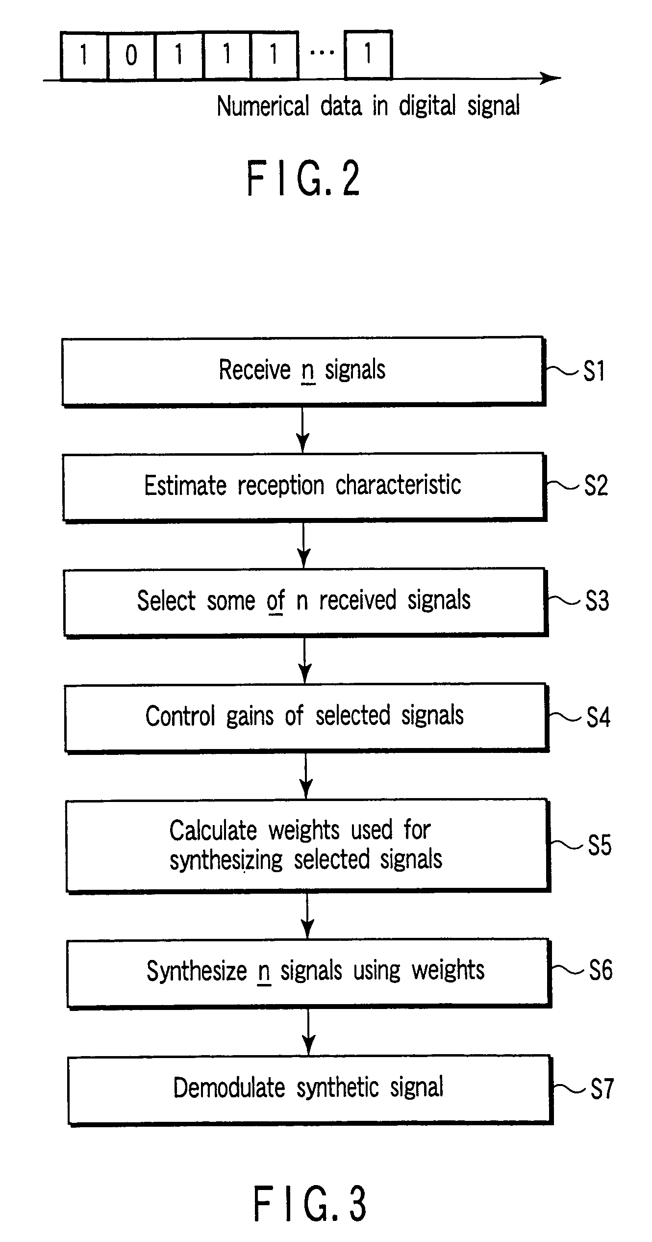
[0029]In the radio receiving apparatus of the embodiment, the receiving characteristic of a to-be-demodulated signal is estimated, and a combination of received signals that enhances the receiving characteristic is selected. Further, the gain of each received signal is controlled, a weight to be imparted to each received signal after gain control is calculated, and a plurality of received signals are synthesized using the calculated weights. As shown in FIG. 1, the radio receiving apparatus comprises a plurality of antenna elements 1 (assume that the embodiment employs n (n is a natural number not less than 2) antenna ...


PUM


Abstract

Radio receiving apparatus includes antennas, radio units adjusting gains of received signals, and outputting the adjusted received signals, respectively, converters converting the adjusted received signals into digital signals, selector device which selects several of the digital signals, combination of the selected digital signals exhibiting good receiving characteristic, controller which determines the gains and outputs single control signal included in information of the determined gains to certain radio units, the certain radio units being included in the radio units and connected to certain converters of the converters which output digital signals included in the selected combination, weight calculator which calculates weight for each of the selected digital signals to enhance the receiving characteristic if the controller outputs the single control signal, synthesizer which synthesizes, into synthetic digital signal, digital signals obtained by multiplying each of the selected digital signals by the weight, and demodulator which demodulates the synthetic digital signal.

Description

CROSS-REFERENCE TO RELATED APPLICATIONS[0001]This application is based upon and claims the benefit of priority from the prior Japanese Patent Application No. 2004-017338, filed Jan. 26, 2004, the entire contents of which are incorporated herein by reference.BACKGROUND OF THE INVENTION[0002]1. Field of the Invention[0003]The present invention relates to a radio receiving apparatus having a plurality of antenna elements, and a radio receiving method, and more particularly to a radio receiving apparatus in which a single control signal controls the gains of signals received by a plurality of antenna elements, and a radio receiving method employed in the apparatus.[0004]2. Description of the Related Art[0005]In general, receiving apparatuses for performing demodulation using digital signals must have an A / D converter. Most A / D converters convert, into digital signals, analog signals of only a certain power range. If an analog signal cannot appropriately be converted into a digital signa...

Claims


Application Information

Patent Timeline
Patent Type & Authority Patents(United States)
IPC IPC(8): H04B7/02H04B1/16H04B1/18H04B7/08H04J99/00H04L1/02H04L27/08
CPCH04B7/0874
Inventor AKITA, KOJISATO, KAZUMIITO, KUNIAKITSUJIMURA, AKIHIRO
Owner KK TOSHIBA
Why Eureka
Try Eureka