Inductively coupled plasma reactor for producing nano-powder

a plasma reactor and inductive coupling technology, applied in the field of high-frequency induction plasma reactor apparatus, can solve the problems of inability to manufacture nano-powder in continuous mass, inability to use solid-phase materials in the manufacture of nano-powder, and inability to achieve continuous mass production of nano-powder. , to achieve the effect of preventing growth and adsorption and safely moving molten

Inactive Publication Date: 2008-01-29
NPC CO LTD
View PDF8 Cites 98 Cited by
  • Summary
  • Abstract
  • Description
  • Claims
  • Application Information

AI Technical Summary

Benefits of technology

[0009]It is another object of the present invention to provide a high-frequency induction plasma reactor apparatus having upper and lower reactors arranged in two stages, the lower reactor having a temperature and capacity larger than those of the upper reactor, thereby enabling the complete vaporization of material powder.
[0010]It is further another object of the present invention to provide a high-frequency induction plasma reactor apparatus, which is configured to prevent the growth and adsorption of vaporized nano-powder via the inflow of cryogenic coolant (i.e. argon gas) into the reactor.
[0011]It is another object of the present invention to provide a high-frequency induction plasma reactor apparatus, which is configured to helically guide coolant gas into the reactor, thereby safely moving molten and vaporized nano-powder to a collecting station via the helical motion thereof without agglomeration.

Problems solved by technology

In the conventional reactor, however, several problems may be encountered while using it.
One recurring problem is that the conventional reactor is configured to use only gas-phase or liquid-phase material as a starting raw material and thus solid-phase material is not allowed in the manufacture of nano-powder.
This makes the continuous mass production of nano-powder impossible.
Another shortcoming of the conventional reactor is a limitation of applicable materials.
Further, the conventional reactor is unable to control plasma because the reactor has no separate plasma control device.
Finally, the moisture content percentage within the conventional reactor is insufficient.

Method used


Image

  • Inductively coupled plasma reactor for producing nano-powder
  • Inductively coupled plasma reactor for producing nano-powder
  • Inductively coupled plasma reactor for producing nano-powder

Examples


Embodiment Construction

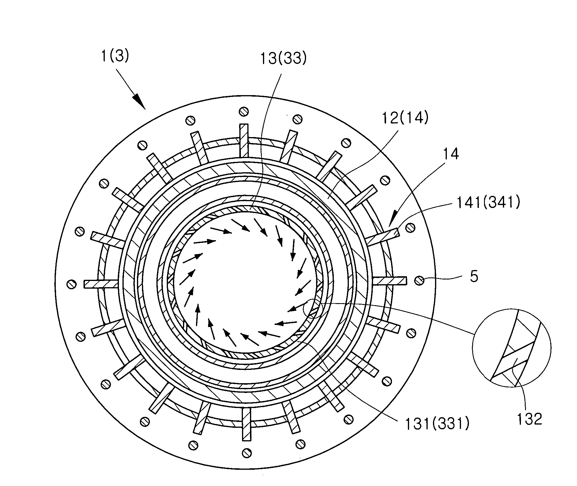
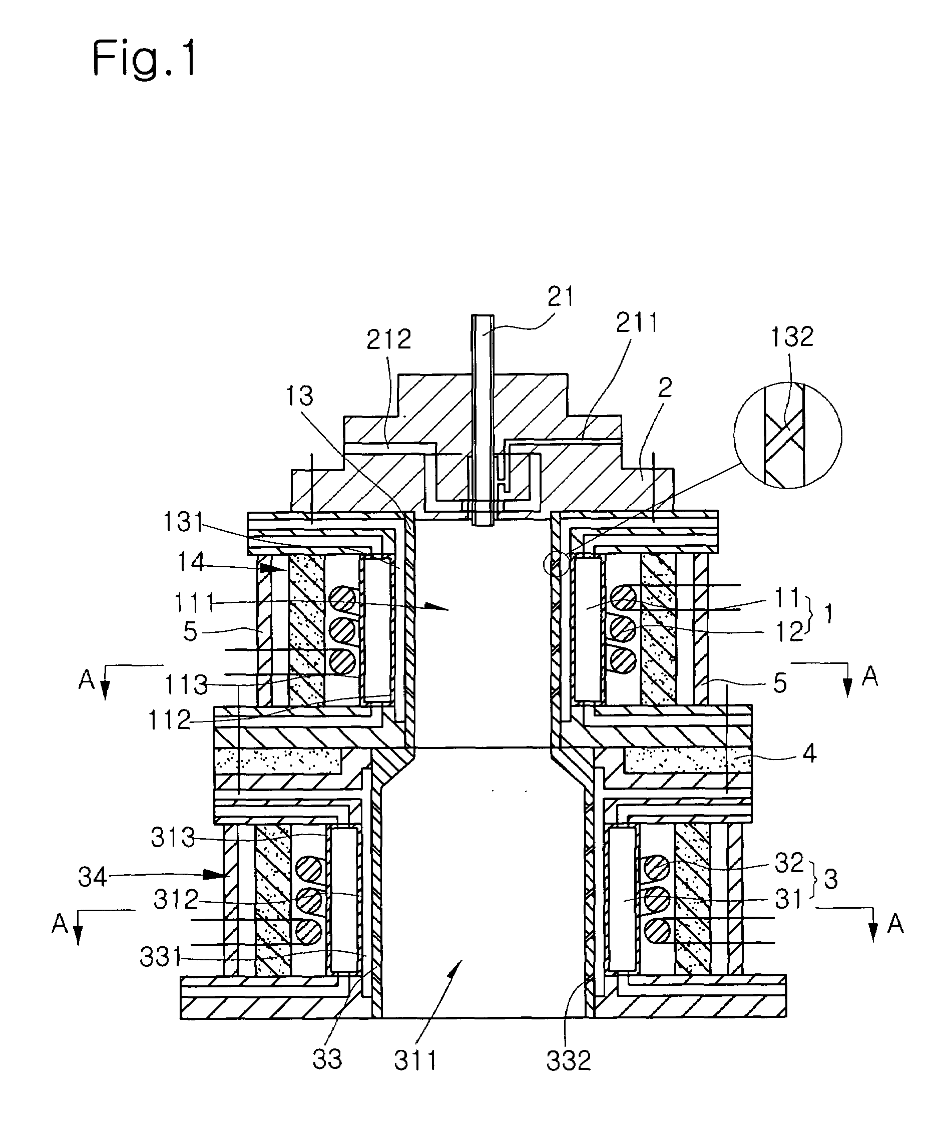
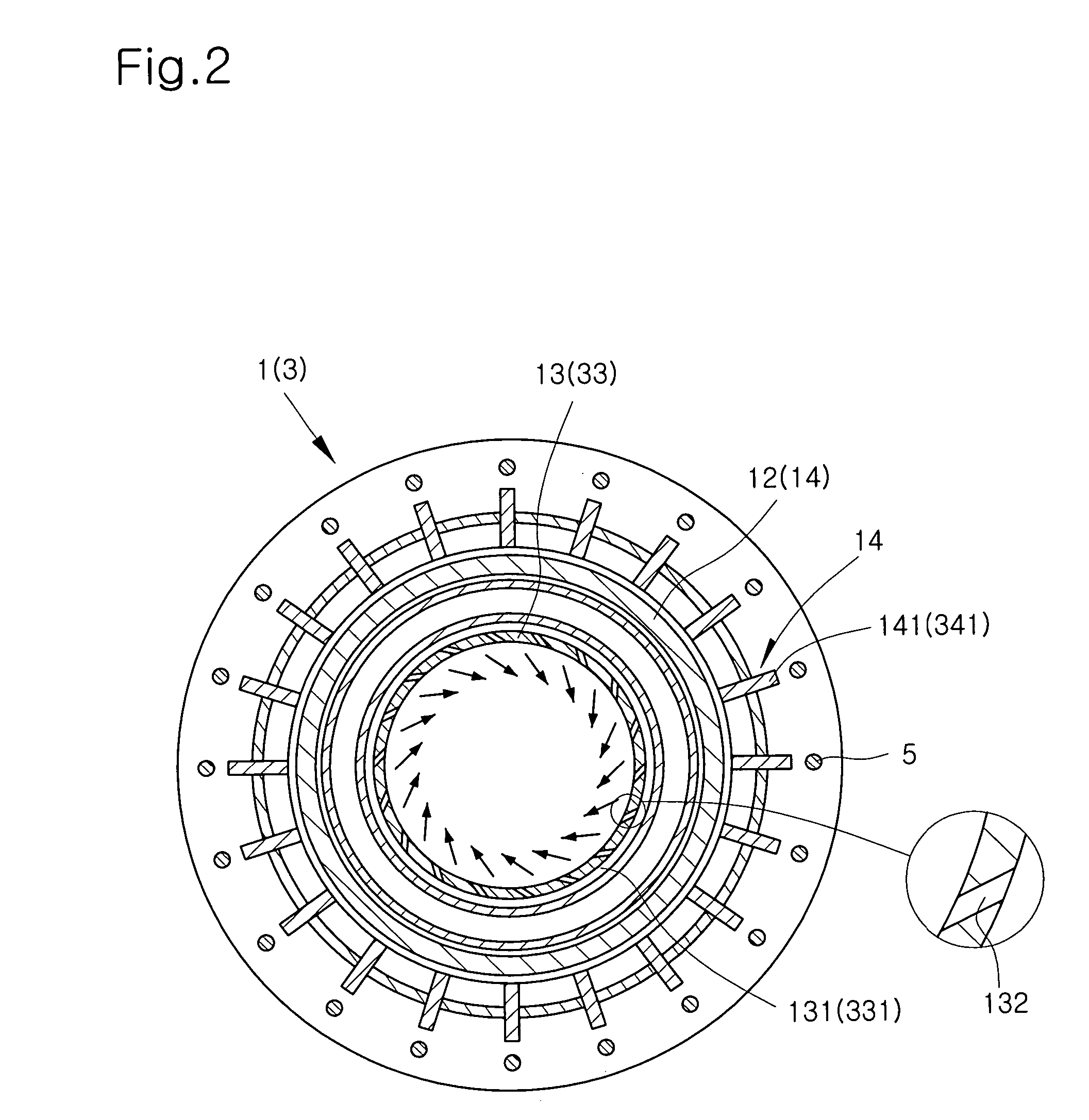
[0020]FIG. 1 is a sectional view illustrating a plasma reactor apparatus in accordance with the present invention, and FIG. 2 is a cross sectional view taken along the line A-A of FIG. 1. First, the configuration of a plasma reactor apparatus will be described.

[0021]Referring to FIGS. 1 and 2, a plasma reactor apparatus of the present invention comprises an upper body 1, a cover 2, and a lower body 3. The upper body 1 is provided with a reaction pipe 11 receiving a reactor 111 extending vertically inside thereof, and a high-frequency coil 12 surrounding the outer periphery of the reaction pipe 11. The cover 2 is mounted to the upper end of the reactor 111 and adapted to seal the reactor 111. The cover 2 has a powder injection tube 21 communicating with the reactor 111 to inject material powder into the reactor 111.

[0022]The lower body 3, located under the upper body 2, is provided with a reaction pipe 31 receiving a reactor 311 extending vertically inside thereof, and a high-frequen...


PUM

PropertyMeasurementUnit
frequencyaaaaaaaaaa
polarityaaaaaaaaaa
diameteraaaaaaaaaa

Abstract

Disclosed herein is a high-frequency induction plasma reactor apparatus for producing nano-powder, which is configured to continuously manufacture nano-powder in large quantities using solid-phase powder as a starting raw material and to manufacture high-purity nano-powder by completely vaporizing the material powder. The high-frequency induction plasma reactor apparatus comprises an upper body and a cover. The upper body is provided with a reaction pipe receiving a reactor extending vertically inside thereof, a high-frequency coil surrounding the outer periphery of the reaction pipe and a ceramic inner wall provided inside the reaction pipe. The ceramic inner wall is formed with a plurality of gas passing bores and defines a gas movement passage with the inner side wall of the reaction pipe therebetween for allowing the inflow of argon gas from the outside into the reactor. The cover is mounted to the upper end of the reactor and adapted to seal the reactor. The cover is provided with a powder injection tube communicating with the reactor.

Description

TECHNICAL FIELD[0001]The present invention relates generally to a plasma reactor apparatus for producing nano-powder at atmospheric pressure using high-frequency coils. More specifically, the present invention relates to a high-frequency induction plasma reactor apparatus for producing nano-powder, which is configured to continuously manufacture nano-powder in large quantities using solid-phase powder as a starting raw material and to manufacture high-purity nano-powder by completely vaporizing the raw material powder.BACKGROUND ART[0002]Generally, a nano-powder producing reactor is referred to an apparatus for manufacturing nano-powder by vaporizing gas-phase or liquid-phase materials as raw materials. The nano-powder manufactured using the reactor is input into and collected in a separate collecting device.[0003]A conventional reactor produces nano-powder by implementing ionization and dissociation of reactants, using plasma torches of direct-current type, high-frequency type, dir...

Claims


Application Information

Patent Timeline
Patent Type & Authority Patents(United States)
IPC IPC(8): B23K10/00B82B3/00B01J19/08H01J37/32H05H1/46
CPCH01J37/321H05H1/46B22F9/12B22F2999/00B22F2202/13B01J19/08B82B3/00B82Y40/00
Inventor KIM, YOUNG-NAM
Owner NPC CO LTD
Why Eureka
Try Eureka