Lens optics used to reduce part deformation due to heat

a technology of lens and heat, applied in the field of lens holder, can solve the problems of short distance between the outer lens, and the inability to place the outer lens too close to the light emitting source, so as to enhance the scattering of light and heat energy, and enhance the scattering effect of ligh

Inactive Publication Date: 2008-04-01
TOYOTA MOTOR CO LTD
View PDF15 Cites 4 Cited by
  • Summary
  • Abstract
  • Description
  • Claims
  • Application Information

AI Technical Summary

Benefits of technology

[0006]According to one aspect of the invention, a lens assembly is provided for use with an automotive vehicle having a light source. The lens assembly includes a reflex lens, a lens holder, an internal lens and a metallic layer. The lens holder has an inner surface facing the light source. The holder has an outer surface opposite the inner surface. The lens holder is adapted for supporting the reflex lens along the outer surface. The internal lens is positioned between the light source and the reflex lens. The internal lens has an undulating surface facing the light source and defined by a plurality of annular bumps. The metallic layer is disposed along the undulating surface to provide enhanced scattering of light and heat energy away from the reflex lens to provide enhanced scattering of light and heat energy away from the reflex lens.

Problems solved by technology

Packaging constraints, due to aesthetics or function, sometimes requires the design of a compact light assembly, resulting in a short distance between the light emitting source and the outer lens.
But, the outer lens cannot be placed too close to the light emitting source due to heat that radiates therefrom.

Method used


Image

  • Lens optics used to reduce part deformation due to heat
  • Lens optics used to reduce part deformation due to heat
  • Lens optics used to reduce part deformation due to heat

Examples


fourth embodiment

[0021]Referring to FIG. 5, a fourth embodiment is shown, wherein like parts from other embodiments described herein are indicated by like numerals offset by 100, a metallic layer 60 is provided along the first surface 322 of the internal lens 320. Preferably, the metallic layer 60 is aluminum. Optionally, the metallic layer 60 is provided on the second surface 324 of the internal lens 320. In use, the metallic layer 60 enhances the tight and heat deflecting function of the internal lens 320. The metallic layer 60 provides still further enhancement of the overall brightness of the light observed coming from the lens assembly 310.

fifth embodiment

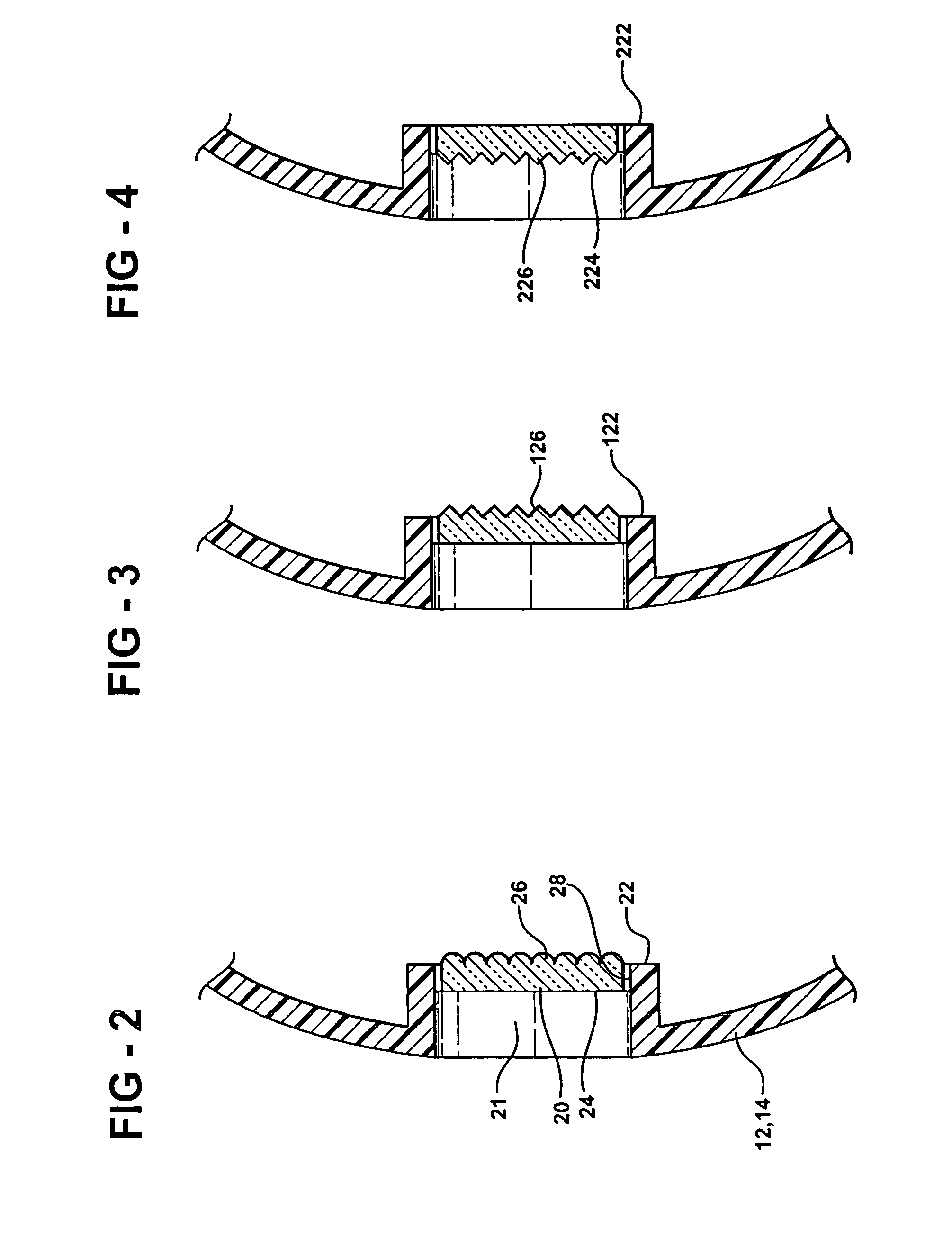
[0022]Referring to FIG. 6, a fifth embodiment is shown, wherein the internal lens 420 has a plurality of annular bumps 70. The bumps 70 are concentric about a central raised bump or portion 72. The bumps 70, form a conical shape raised axially toward the lamp. The metallic layer 460 is provided along the first surface 422 of the internal lens 420. The metallic layer 460 is aluminum, or other suitable light and heat reflecting material known to those having ordinary skill in the art. The metallic layer 460 follows the bumps along the cross section of the internal lens 420, thereby providing enhanced light and heat scattering characteristics over the previous embodiment.


PUM


Abstract

A light assembly for an automotive vehicle includes a lens holder that supports an internal lens. The light assembly includes a light source powered by the vehicle. The internal lens includes an undulating surface facing the light source. A reflective metallic layer is disposed along the undulating surface to provide enhanced scattering of light and heat away from a reflex lens.

Description

CROSS REFERENCE TO RELATED APPLICATIONS[0001]This application is a continuation-in-part of U.S. patent application Ser. No. 11 / 151,607 filed on Jun. 13, 2005, the contents of which are incorporated herein by reference in its entirety.BACKGROUND OF THE INVENTION[0002]1. Field of the Invention[0003]The invention relates to light assemblies for automotive vehicles. More particularly, the invention relates to a lens holder having an inner lens for diffusing heat emitted from a light source.[0004]2. Description of the Related Art[0005]Automotive vehicles include light assemblies for providing indicator signals visible to persons in other vehicles or as pedestrians. A light assembly typically includes a housing defining an enclosed space and a socket for supporting a light emitting source, such as an incandescent bulb, within the enclosed space. The housing also includes an outer lens that is colored according to its specific function, such as red for a stop signal and yellow or orange fo...

Claims


Application Information

Patent Timeline
Patent Type & Authority Patents(United States)
IPC IPC(8): F21V5/00
CPCF21S48/2212F21S48/255F21S48/337F21S48/32F21S48/325F21S48/328F21V5/04F21V29/004F21S43/26F21S43/51F21S45/10F21S45/37F21V29/504F21S45/40F21S45/43F21S45/47
Inventor READING, PAUL ANTHONY
Owner TOYOTA MOTOR CO LTD
Why Eureka
Try Eureka