
Glass composite particles and uses thereof

a composite particle and glass technology, applied in the field of composite particles, can solve the problems of inability to enable the long-term performance required of a product for display devices or lighting devices, and ineffective protection of said surface, etc., to achieve enhanced light flux resistance, enhanced stability over temperature, and enhanced resistance to photobleaching

Active Publication Date: 2019-08-29
NEXDOT
View PDF0 Cites 5 Cited by
  • Summary
  • Abstract
  • Description
  • Claims
  • Application Information

AI Technical Summary

Benefits of technology

The patent describes a new type of small chemical particle that can be used to calibrate optical instruments. These particles are stable and can be stored for a long time, making them ideal for use in laboratory settings. The particles scatter light better than larger particles, which makes them easier to use. They also create more stable dispersions in solvents, which makes them compatible with the pixels of optical instruments. Overall, this new technology allows for more precise and accurate calibration of spectrophotometers.

Problems solved by technology

However, the ligands commonly used to functionalize the surface of inorganic nanoparticles allow deteriorating species or harmful compounds to attack said surface, thus do not protect efficiently said surface and do not enable the long-term performance required of a product for display devices or lighting devices.
However, said particles are mesoporous which means that they comprise a porous network that allows access to the quantum dots surface for deteriorating species, like water and oxygen, or other harmful compounds.
The protection of said surface is thus ineffective and does not enable a long-term stability in time and temperature.
However, cracks and defects are often generated in such conversion layers, leaving the encapsulated inorganic nanoparticles surface bare to the attack of deteriorating species, like water and oxygen, or other harmful compounds.
The protection of said surface is thus ineffective and does not enable a long-term stability in time and temperature.
Particles disclosed have a size ranging from 0.5 to 200 μm, such a big size can complicate the dispersion of said particles in solution or in a matrix, result in poor light scattering, or be incompatible with small pixels.
Furthermore, document WO2015 / 077372 does not disclose the evolution of photoluminescence properties (emission spectra, full width half maximum or PLQY) of the quantum dots before and after encapsulation in glass.
In such a method, it is very difficult to control the growth of said quantum dots.
Indeed, disclosed CdSeS quantum dots have a broad size distribution which badly affect their photoluminescence properties.
However, this method does not provide an efficient protection against environmental deteriorating species especially, such as water and oxygen, or other harmful compounds as quantum dots stay accessible in the pores.
Furthermore, this method does not result in a particle but in a piece of glass that would not be usable in lightning displays, in particular for deposition on pixels.
However, this method results in non-vitrified glass, and the use of surfactants such as Igepal will lead to the formation of mesoporosity in said particles.
The protection of said surface is thus ineffective and does not enable a long-term stability in time and temperature.

Method used


Image

  • Glass composite particles and uses thereof
  • Glass composite particles and uses thereof
  • Glass composite particles and uses thereof

Examples


example 1

Inorganic Nanoparticles 13 Preparation

[1416]CdSe Nanoplatelets

[1417]170 mg of cadmium myristate (Cd(myr)2) (0.3 mmol) and 15 mL of octadecene (ODE) are introduced in a three neck flask and are degassed under vacuum. The mixture is heated under agron flow at 250° C. and 1 mL of a dispersion of Se 100 mesh sonicated in ODE (0.1 M) are quickly injected. After 30 seconds, 80 mg of cadmium acetate (Cd(OAc)2) (0.3 mmol) are introduced. The mixture is heated for 10 minutes at 250° C.

[1418]CdSe@CdZnS Nanoplatelets

[1419]In a three neck flask, 15 mL of trioctylamine are introduced and degassed under vacuum at 100° C. Then the reaction mixture is heated at 300° C. under argon and 5 mL of CdSe nanoplatelets in octadecene (ODE) are swiftly injected followed by the injection of 7 mL of 0.1 M octanethiol solution in ODE, 3.5 mL of 0.1 M cadmium oleate (Cd(OA)2) in ODE and 3.5 mL of 0.1M zinc oleate (Zn(OA)2) in ODE with syringe pumps at a constant rate over 90 min. After the addition, the reaction...

example 2

Composite Particles 1 Preparation—CdSe@CdZnS@SiO2

[1432]10 μL of silanized CdSe@CdZnS nanoplatelets suspended in toluene (1.0 μM) were added into a solution of 200 μL of deionized water, 50 μL of acetic acid, 150 μL of TEOS and 5 mL of tetrahydrofuran previously prepared and stirred for 24 h. The mixture was then introduced into an atomization chamber and atomized through a tube furnace heated at 300° C. with a nitrogen flow of 40 cm3 / s, as described in the invention. The composite particles 1 were collected at the surface of a PTFE hydrophilic filter with a pore size of 200 nm and then suspended in acetone using sonication for 10 minutes.

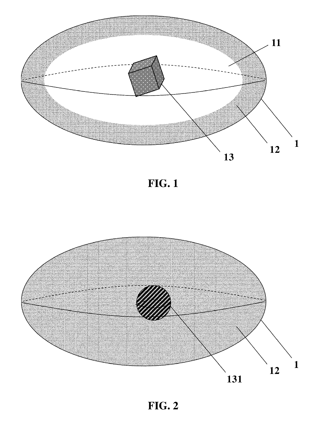
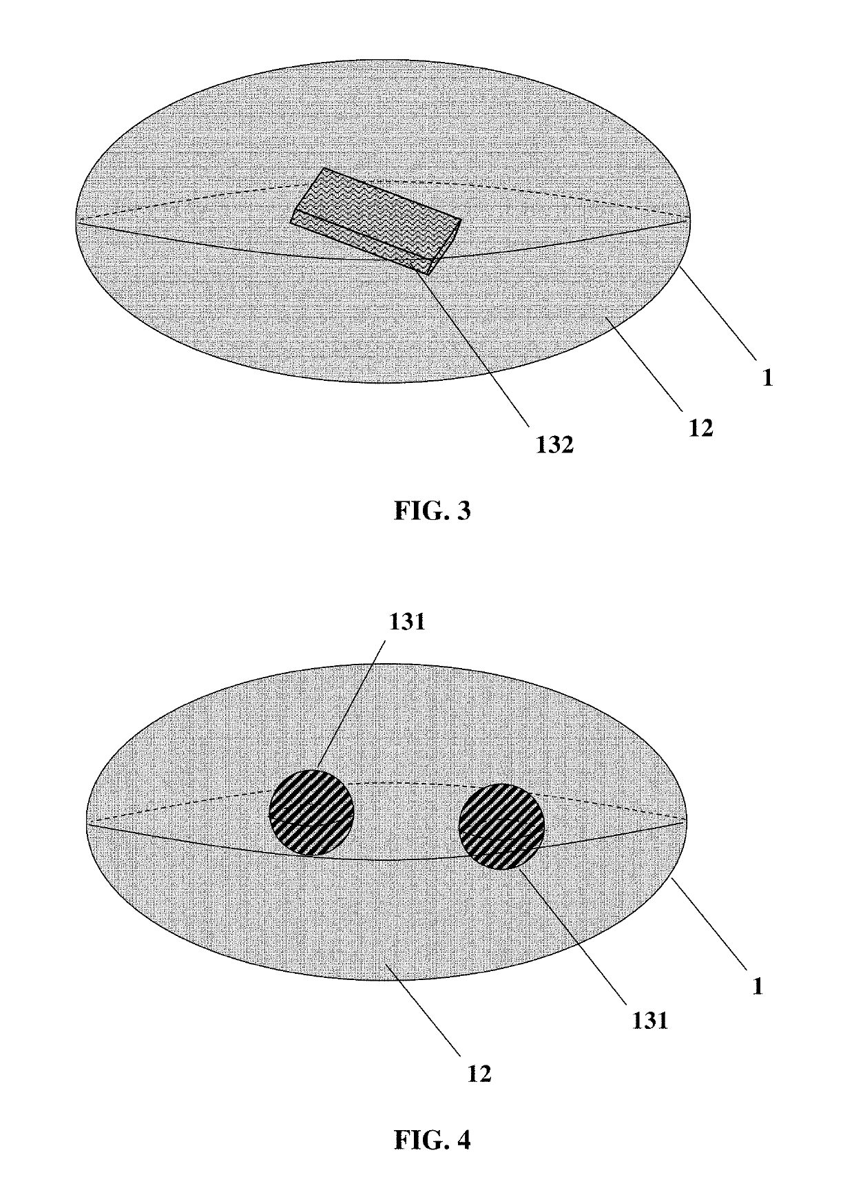
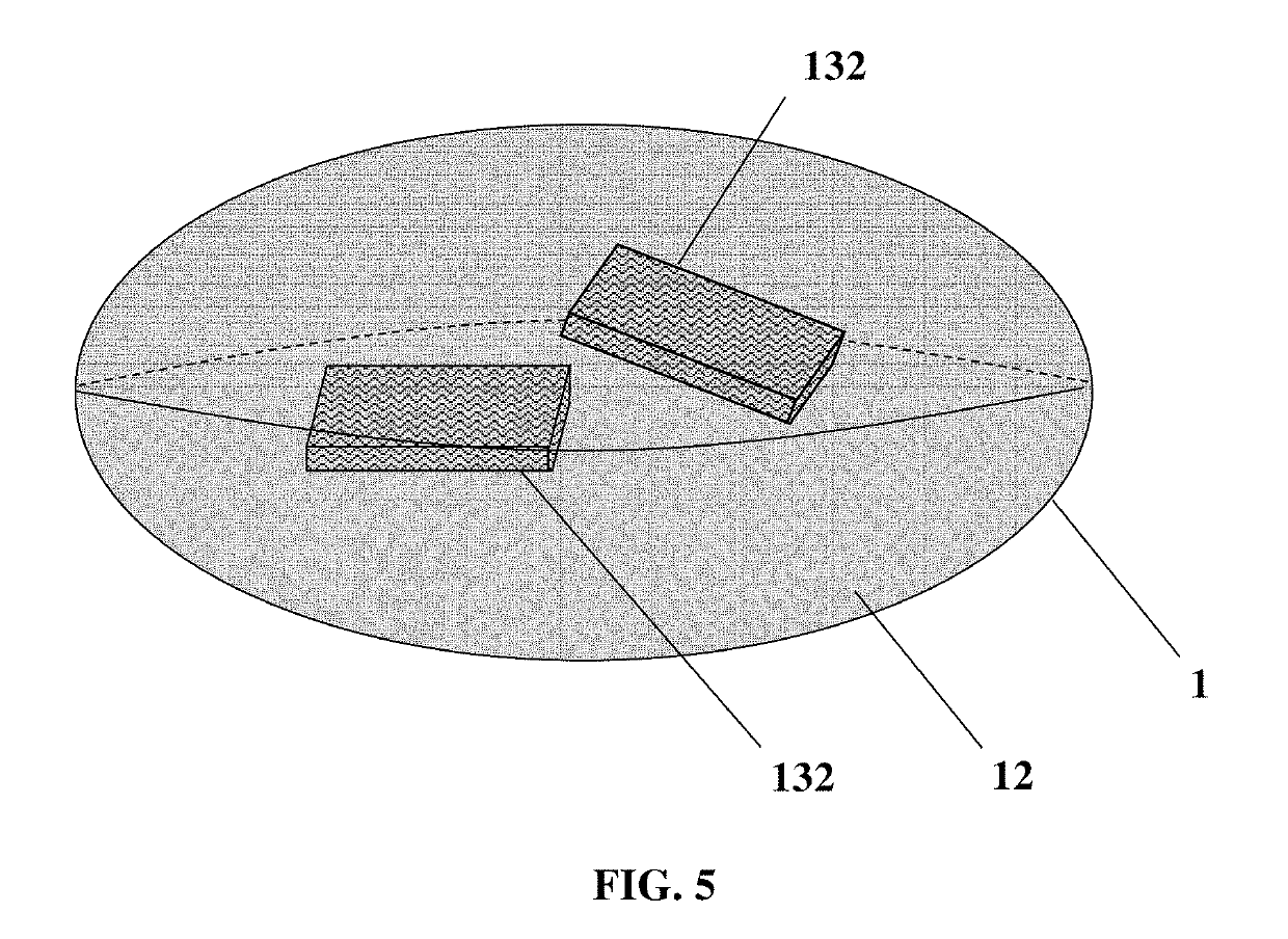
[1433]In FIG. 12, TEM images show inorganic nanoparticles 13 (dark contrast) clearly embedded in a silica shell 12 (bright contrast).

example 3

Composite Particles 1 Preparation—CdSe@CdZnS@SixNayCazOv

[1434]100 μL of CdSe@CdZnS nanoplatelets suspended in tetrahydrofuran (1.0 μM), 200 μL of deionized water, 10 μL of acetic acid, 400 μL of polydiethoxysilane, 5 mg of calcium nitrate and 3 mg of sodium nitrate were added into an atomization chamber. After 10 minutes of magnetic stirring, the liquid mixture was sprayed towards a tube furnace heated at 525° C. with a nitrogen flow of 30 cm3 / s, as described in the invention. The composite particles 1 were collected at the surface of a filter with a pore size of 1 μm and then suspended in ethanol using sonication for 10 minutes.


PUM

PropertyMeasurementUnit
Diameteraaaaaaaaaa
Diameteraaaaaaaaaa
Sizeaaaaaaaaaa

Abstract

A composite particle including a core and a shell, wherein the core has at least one inorganic nanoparticle and the shell is made of vitrified glass, methods for obtaining thereof and uses thereof. The uses include a film having a host material and at least one composite particle and an optoelectronic devise including at least one composite particle or the film.

Description

FIELD OF INVENTION[0001]The present invention relates to composite particles comprising a core and a shell, wherein the core comprises at least one inorganic nanoparticle and the shell is made of vitrified glass.BACKGROUND OF INVENTION[0002]To represent the colors in all their variety, one proceeds typically by additive synthesis of at least three complementary colors, especially red, green and blue. In a chromaticity diagram, the subset of available colors obtained by mixing different proportions of these three colors is formed by the triangle formed by the three coordinates associated with the three colors red, green and blue. This subset constitutes what is called a gamut.[0003]The majority of color display devices operate on this three-color principle: each pixel consists of three sub-pixels, one red, one green and one blue, whose mixture with different intensities can reproduce a colorful impression.[0004]A luminescent or backlit display such as a computer LCD screen has to pre...

Claims


Application Information

Patent Timeline
IPC IPC(8): C09K11/02C09K11/59
CPCC09K11/025C09K11/595B82Y40/00B82Y20/00C03C4/12C09K11/02C03C1/008C03C14/006
Inventor POUSTHOMIS, MARCD'AMICO, MICHELE
Owner NEXDOT
Learn More