Luminous systems

a technology of luminous systems and light sources, applied in the field of luminous systems, can solve the problems of difficulty in manipulating the reflected light of the system, observed visible color produced when the white illumination source is non-powered, and significant energy loss, so as to increase the photolytic and thermal stability of the multilayer structure, increase optical scattering, and increase the effect of optical scattering

Active Publication Date: 2017-10-24
BAMBU VAULT LLC
View PDF49 Cites 5 Cited by
  • Summary
  • Abstract
  • Description
  • Claims
  • Application Information

AI Technical Summary

Benefits of technology

[0006]The present teachings provide for a luminous system comprising one or more illumination sources that output, when powered, a primary electromagnetic radiation through one or more exit regions, a multilayer structure, and one or more diffuse reflection layers that are optically decoupled from the multilayer structure and redirect at least a portion of ambient electromagnetic radiation to the viewing hemisphere. The emission and the reflection of the luminous system produce a first observed visible color when the one or more illumination sources are powered and a second observed visible color when the one or more illumination sources are non-powered. In some instances the first observed visible color and the second observed visible color may be substantially similar. The one or more illumination sources of the present teachings comprise one or more light emitting elements. The one or more illumination sources may further comprise one or more optical elements that receive and propagate at least a portion of the primary electromagnetic radiation emitted from the one or more light emitting elements and substantially transmit the primary electromagnetic radiation through said one or more exit regions to the multilayer structure. The one or more optical elements may comprise one or more light guides having a surface with one or more extraction regions. In some aspects, the one or more extraction regions of the surface of the one or more light guides may be remote to the one or more light emitting elements. In certain constructions, the one or more illumination sources may further optionally comprise a reflection layer that redirects at least a portion of the primary electromagnetic radiation to the viewing hemisphere. The multilayer structure of the present teachings comprises one or more energy conversion layers that convert at least a portion of incident radiation to a secondary electromagnetic radiation that is at least partially emitted to the viewing hemisphere, wherein the incident radiation is at least one of the primary electromagnetic radiation or ambient electromagnetic radiation. In some instances, the one or more energy conversion layers may optionally comprise one or more light scattering materials that disperse at least a portion of radiation, in which the radiation is at least one of the primary electromagnetic radiation or the secondary electromagnetic radiation. The multilayer structure also comprises one or more diffusion layers that substantially increase optical scattering of at least a portion of radiation, wherein the radiation is at least one of the primary electromagnetic radiation, the secondary electromagnetic radiation, or ambient electromagnetic radiation. The one or more diffusion layers may, in some aspects, additionally fulfill the function of a protection layer that provides physical and chemical durability for the multilayer structure. The multilayer structure of the present teachings may be optically coupled to the one or more illumination sources, whereas in other instances may be optically decoupled. In some aspects, the multilayer structure of the present teachings may further comprise a reflection layer that redirects at least a portion of the secondary electromagnetic radiation to the viewing hemisphere, wherein the reflection layer is substantially transmissive of the primary electromagnetic radiation. In other aspects, the multilayer structure of the present teachings may also comprise one or more stability enhancement layers that increase photolytic and thermal stability of the multilayer structure. In another aspect, the multilayer structure may additionally comprise a protection layer that provides physical and chemical durability for the multilayer structure.

Problems solved by technology

Unfortunately, this approach to color generation results in substantial loss of energy due firstly, to the amount of energy needed to create the white light, and secondly, to the additional energy lost in the subtraction of the wavelengths to create a colored emission.
This can be a particular problem when the white illumination source does not contain sufficient energy of the desired color, such as for example in the case of white light LEDs that provide only modest amounts of energy at red wavelengths.
An additional drawback to utilizing white illumination sources is the difficulty in manipulation of the reflected light of the system, therefore suffering from the limitation that the observed visible color produced when the white illumination sources are non-powered must be substantially the same as the observed color when the illumination sources are powered.
This is due to the color generation mechanism of the system since wavelengths associated with that of the white illumination source are similar to those associated with the ambient light, therefore making it difficult to tailor the emission of the system without affecting the reflection of the system and vice versa.
Although these systems may be more efficient in generating light than those which utilize white light sources, when these systems are non-powered, the observed visible color of the system is also difficult to tailor to a desired observed visible color.
For example, the absorption of blue light by the energy conversion layer causes the reflectance of the surface of the system to appear yellowish when the primary electromagnetic radiation is not supplied, i.e. the illumination source(s) are non-powered, resulting in an undesirable observed visible color.

Method used


Image

  • Luminous systems
  • Luminous systems
  • Luminous systems

Examples


example 1

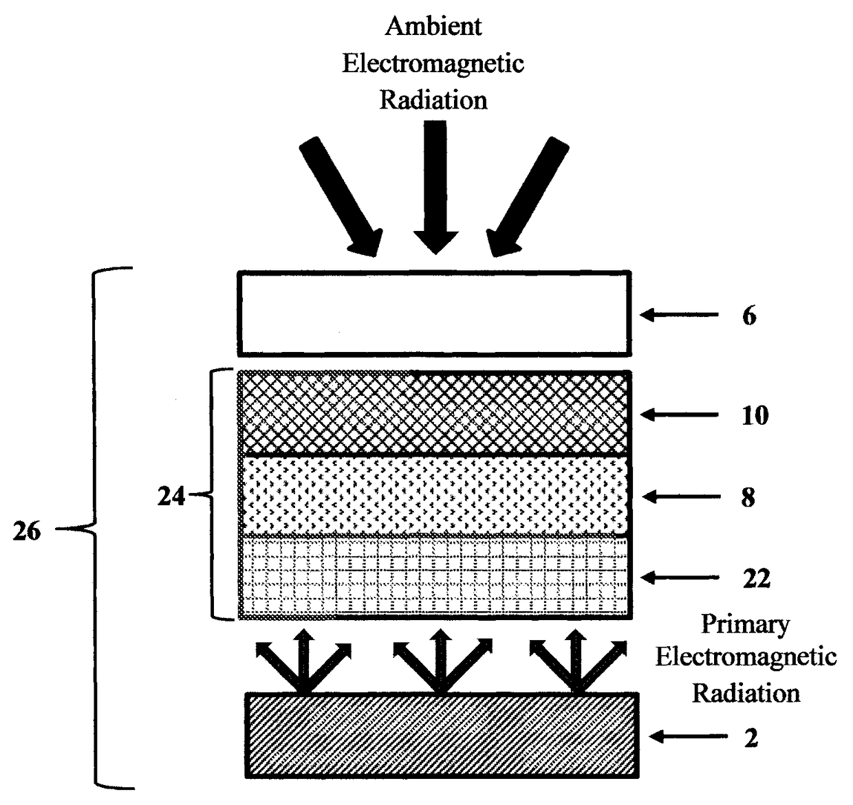
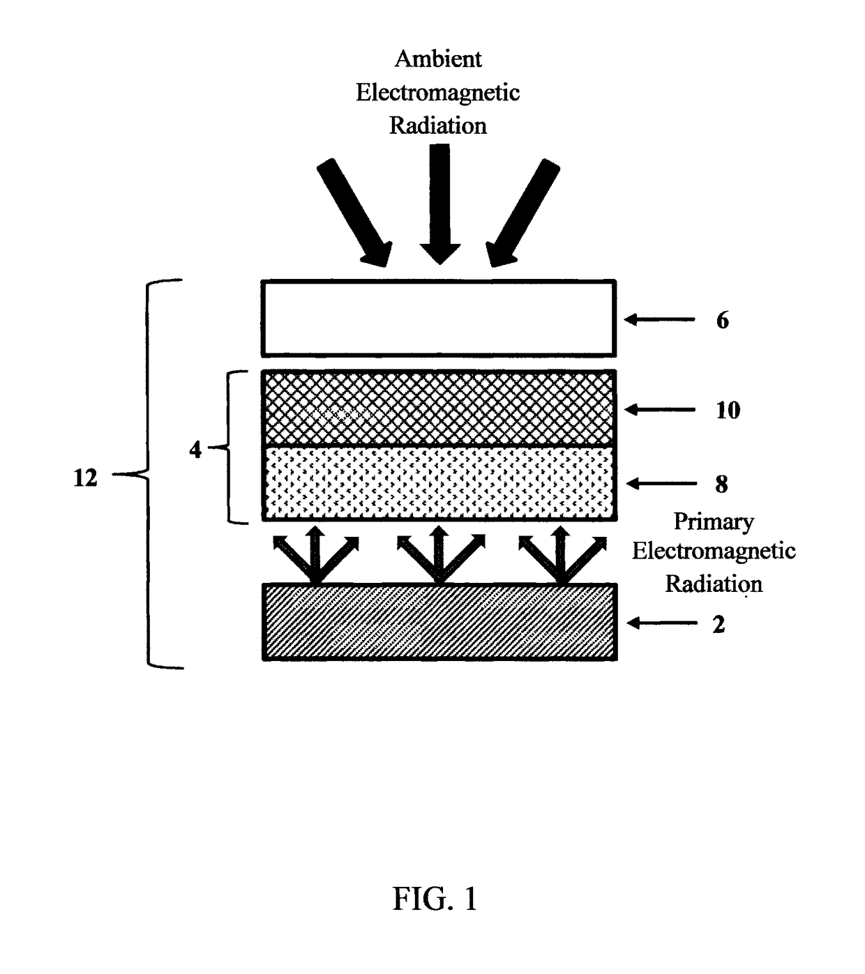
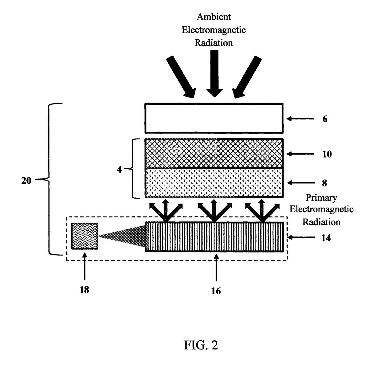
on of Diffusion Layer (Characterized as 10 in FIGS. 1, 2, and 5-7)

[0095]A formulation containing 0.9120 parts screen printing ink, such as Automark APL Dye-Based Clear, 0.00502 parts defoamer, such as Tego® Foamex N, 0.00201 parts of wetting agent, such as Tego® Wet 270, 0.00575 parts titanium dioxide, 0.000182 parts dispersant, such as DisperBYK® 112, and 0.0751 parts spherical glass beads, such as Sphericel® 110P8, was prepared and stirred at room temperature. The formulation was screen printed onto 10 mil carrier substrate, such as a clear polyester substrate (Mylar), through a 60 mesh steel screen and dried at 80° C. for 30 minutes to yield a 2.3 mil or 58 micron thick, diffusion layer.

example 2

on of Energy Conversion Layer (Characterized as 8 in FIGS. 1, 2, and 5-7) and Preparation of Multilayer Structure (Characterized as 4 in FIGS. 1 and 2)

[0096]A formulation containing 0.9535 parts screen printing ink, such as Automark APL Dye-Based Clear, 0.00449 parts defoamer, such as Tego® Foamex N, 0.00220 parts of wetting agent, such as Tego® Wet 270, and 0.000195 parts 3-cyanoperylene-9,10-dicarboxylic acid 2′,6′-diiosopropylanilide in 0.0389 parts dioxolane, and 0.00045 parts 3,4,9,10-perylene tetracarboxylic acid bis(2′,6′-diisopropyl) anilide was prepared and stirred at room temperature. The formulation was printed onto the diffusion layer prepared in Example 1 through a 60 mesh steel screen and dried at 80° C. for 60 minutes to yield a 1 mil or 25 micron thick, yellow daylight color energy conversion layer coupled to the diffusion layer, thereby resulting in a multilayer structure.

example 3

on of Diffuse Reflection Layer (Characterized as 6 in FIGS. 1, 2, and 5-7)

[0097]A formulation containing 0.9747 parts screen printing ink, such as Automark APL Dye-Based Clear, 0.00509 parts defoamer, such as Tego® Foamex N, 0.00201 parts of wetting agent, such as Tego® Wet 270, 0.0166 parts titanium dioxide, and 0.00166 parts dispersant, such as DisperBYK® 112 was prepared and stirred at room temperature. The formulation was screen printed onto 10 mil carrier substrate, such as a clear polyester substrate (Mylar), through a 60 mesh steel screen and dried at 80° C. for 30 minutes to yield a diffusion reflection layer.


PUM

PropertyMeasurementUnit
wavelengthsaaaaaaaaaa
angleaaaaaaaaaa

Abstract

A luminous system comprising one or more illumination sources, a multilayer structure, and one or more diffuse reflection layers being optically decoupled from the multilayer structure, wherein the emission and the reflection of the luminous system produce a first observed visible color when the one or more illumination sources are powered and a second observed visible color when the one or more illumination sources are non-powered is disclosed. Also disclosed are methods of creating the inventive luminous system.

Description

BACKGROUND OF THE INVENTION[0001]These teachings relate generally to luminous systems that provide observed visible color, and more particularly to a luminous system that provides a first observed visible color that is primarily produced by the emission of the system when such system is powered, and also provides a second observed visible color that is primarily produced by the reflection of the system when such system is non-powered.[0002]The primary purpose of luminous systems is to generate light of certain desired visible color(s), white, blue, green, etc., with the use of illumination source(s), e.g. LEDs, for a broad range of applications, e.g. general lighting, illuminated graphics, etc. Thus, when the illumination source(s) are powered, the observed visible color of such systems is predominantly a result of the emission produced by the system. However, when the illumination sources are non-powered, the observed visible color of such systems is mainly produced by way of ambie...

Claims


Application Information

Patent Timeline
Patent Type & Authority Patents(United States)
IPC IPC(8): F21V7/00F21K9/90G02F2/00G02F2/02F21V8/00
CPCF21V7/00F21K9/90G02F2/02G02F2/004Y10T29/49002G02B6/0055
Inventor HORNER, M. GLENNKINGSLEY, EDWARD D.AGRAWAL, SATISHCINCOTTA, LOUIS
Owner BAMBU VAULT LLC
Why Eureka
Try Eureka