Printing tape, tape cartridge provided therewith, and tape printing apparatus

a technology which is applied in the direction of inking apparatus, identification means, instruments, etc., can solve the problems of inability to prepare laminated printing tape, no mechanism for adhesion of printing tape and laminating tape,

Inactive Publication Date: 2008-04-15
SEIKO EPSON CORP
View PDF25 Cites 98 Cited by
  • Summary
  • Abstract
  • Description
  • Claims
  • Application Information

AI Technical Summary

Benefits of technology

[0006]In view of the above-described problem, this invention has an advantage of providing a printing tape which is capable of laminating the printed surface with a printing tape itself after printing, without providing a tape printing apparatus with a mechanism for paying out a laminate tape and laminating it with the printed tape. This invention also provides a tape cartridge and a tape printing apparatus for mounting thereon the tape cartridge.
[0012]According to the above-described arrangement, since the print-recording piece and the cut-off piece are formed in a ratio of about 2:1 in width, the printing tape can be prevented from becoming easily peeled off due to too small an adhesive region as compared with the printing region. The printing region can also be prevented from becoming small due to too large an adhesive region as compared with the printing portion. The printing region and the adhesive margin can thus be formed in an appropriate ratio.
[0014]According to the above-described arrangement, the user can perform the peeling operation while referring to the operating information about the peeling operation. The user can easily form the laminated printing tape without wrong peeling operation. As the operating information, there may be used patterns such as symbols, shading, oblique lines, or the like, aside from the characters.
[0018]According to the above-described arrangement, printing is made on the printing tape which is capable of laminating, with the printing tape itself after printing, the printing surface having printed thereon the character string. Therefore, the laminated printing tape can be easily formed. Further, since the printing tape has the adhesive-agent layer, it can be adhered to an object of adhesion right after printing. In addition, since the printing is made with the width of the print-recording piece as the printing region (print-width region) in the widthwise direction of the tape, there is no possibility that the characters are printed on the cut-off pieces to be peeled off from the adhesive-agent layer. In addition, since the inputted character string is printed after inverting it in the right-and-left direction, in the case of the printing tape to be adhered to the object of adhesion in a state of inverting inside out, the printed character string will look toward the correct direction (become a true image) in a state of being adhered, thereby facilitating easy recognition. Preferably, the character string is printed with due centering relative to the printing region (print-width region) as seen in the widthwise direction of the tape.
[0022]According to the above-described arrangement, in the printed and cut printing tape, the user can perform the peeling operation by referring to the operating information about the peeling operation. Therefore, the laminated printing tape can be easily formed without wrong peeling operation.

Problems solved by technology

In the former example, on the other hand, there is no mechanism for adhering the printing tape and the laminating tape together.
Therefore, even if a tape cartridge having added thereto the laminating tape is loaded, a laminated printing tape cannot be prepared.

Method used


Image

  • Printing tape, tape cartridge provided therewith, and tape printing apparatus
  • Printing tape, tape cartridge provided therewith, and tape printing apparatus
  • Printing tape, tape cartridge provided therewith, and tape printing apparatus

Examples


Embodiment Construction

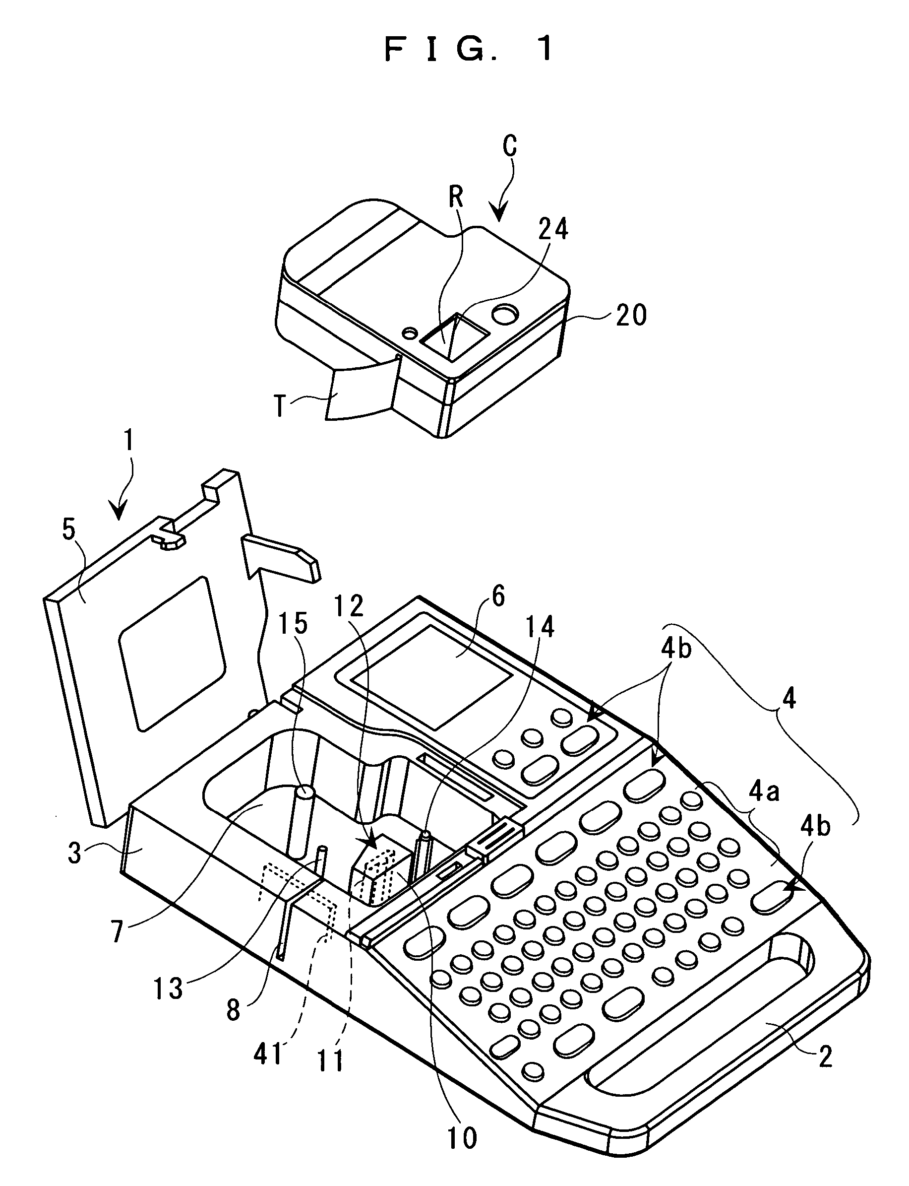
[0033]With reference to the accompanied drawings, a description will now be made about a printing tape, a tape cartridge, and a tape printing apparatus according to one embodiment of this invention.

[0034]FIG. 1 is an external perspective view of a tape printing apparatus 1 in a state in which a lid is left open. The tape printing apparatus 1 has an external shell which is formed by an apparatus case 3. A keyboard 4 having arranged therein various input keys is disposed in a front upper surface of the apparatus case 3, and an opening / closing lid 5 is disposed in a rear upper surface at the left-half portion thereof, and a display 6 is disposed at the right-half thereof. The term “front” means a side closer to an operator and the term “rear” means a side remote from the operator. Inside the opening / closing lid 5 is disposed a cartridge mounting block 7 for mounting therein in an embedded manner a tape cartridge C which contains therein a tape T and an ink ribbon R. The tape cartridge ...


PUM


Abstract

A printing tape has a translucent recording-tape layer with a recording surface on a face thereof, and a translucent pseudo-laminating layer adhered to a back of the recording-tape layer. The pseudo-laminating layer has an adhesive-agent layer on a face thereof and a translucent tape layer on a back thereof. The recording-tape layer has a print-recording piece whose face serves as a printing region and a cut-off piece to be peeled off from the adhesive-agent layer. The print-recording piece is separated from the cut-off piece by a long-side cutting line formed in a longitudinal direction of the recording surface. By inverting both the recording-tape layer and the pseudo-laminating layer inside out for adhering to an object of adhesion after removing the cut-off piece, the pseudo-laminating layer serves as a laminate tape for the recording surface.

Description

BACKGROUND OF THE INVENTION[0001]1. Field of the Invention[0002]This invention relates to a printing tape which partially serves as a laminate tape, a tape cartridge, and a tape printing apparatus.[0003]2. Description of the Related Art[0004]Conventionally, there are two kinds of tape cartridges, one having contained a printing tape and an ink ribbon inside a cartridge case in a manner to be freely pulled out therefrom, and the other having contained a printing tape, a laminating tape and an ink ribbon inside a cartridge case in a manner to be freely pulled or paid out therefrom. These two kinds of tape cartridges are respectively loaded into an exclusively used tape printing apparatus. In the former example, the printing onto the printing tape and the tape cutting are performed to thereby prepare a label. In the latter example, the printing on the printing tape, the adhesion of the laminating tape, and the tape cutting are performed to prepare a laminated printing tape.[0005]In the...

Claims


Application Information

Patent Timeline
Patent Type & Authority Patents(United States)
IPC IPC(8): B41J11/70B41J11/68B41J3/36
CPCB41J3/4075B41J15/044Y10T428/15B41J31/05B41J32/00
Inventor KURASHINA, HIROYASU
Owner SEIKO EPSON CORP
Why Eureka
Try Eureka