Droplet ejection device

a technology of droplet and ejection device, which is applied in the direction of printing, printing, inking apparatus, etc., can solve the problems of complicated control system, inability to manufacture print heads at a low cost, and inability to perform high-speed printing operations, etc., and achieves low cost, high resolution, and relatively simple construction.

Inactive Publication Date: 2008-06-03
BROTHER KOGYO KK
View PDF6 Cites 13 Cited by
  • Summary
  • Abstract
  • Description
  • Claims
  • Application Information

AI Technical Summary

Benefits of technology

[0008]It is therefore an object of the present invention to provide a droplet ejection device which is made relatively simple in construction at a low cost and which is capable of forming a desired image with high resolution at a high speed. This object may be achieved according to any one of first through fourth aspects of the invention which are described below.

Problems solved by technology

Where the print head is provided by the serial head, there is a problem that the printing operation can not be performed at a high speed since the print head has to be reciprocated many times. Where the print head is provided by the line head, there is a problem that the print head can not be manufactured at a low cost since a large number of nozzles are necessarily arranged on the print head.
In the inkjet printer, however, the timing and velocity of the ejection of each ink droplet have to be controlled with considerably high accuracy requiring a complicated control system.
Further, even if the complicated control system is established in the printer, the ejection control can not be achieved with high degree of freedom.

Method used


Image

  • Droplet ejection device
  • Droplet ejection device
  • Droplet ejection device

Examples


first embodiment

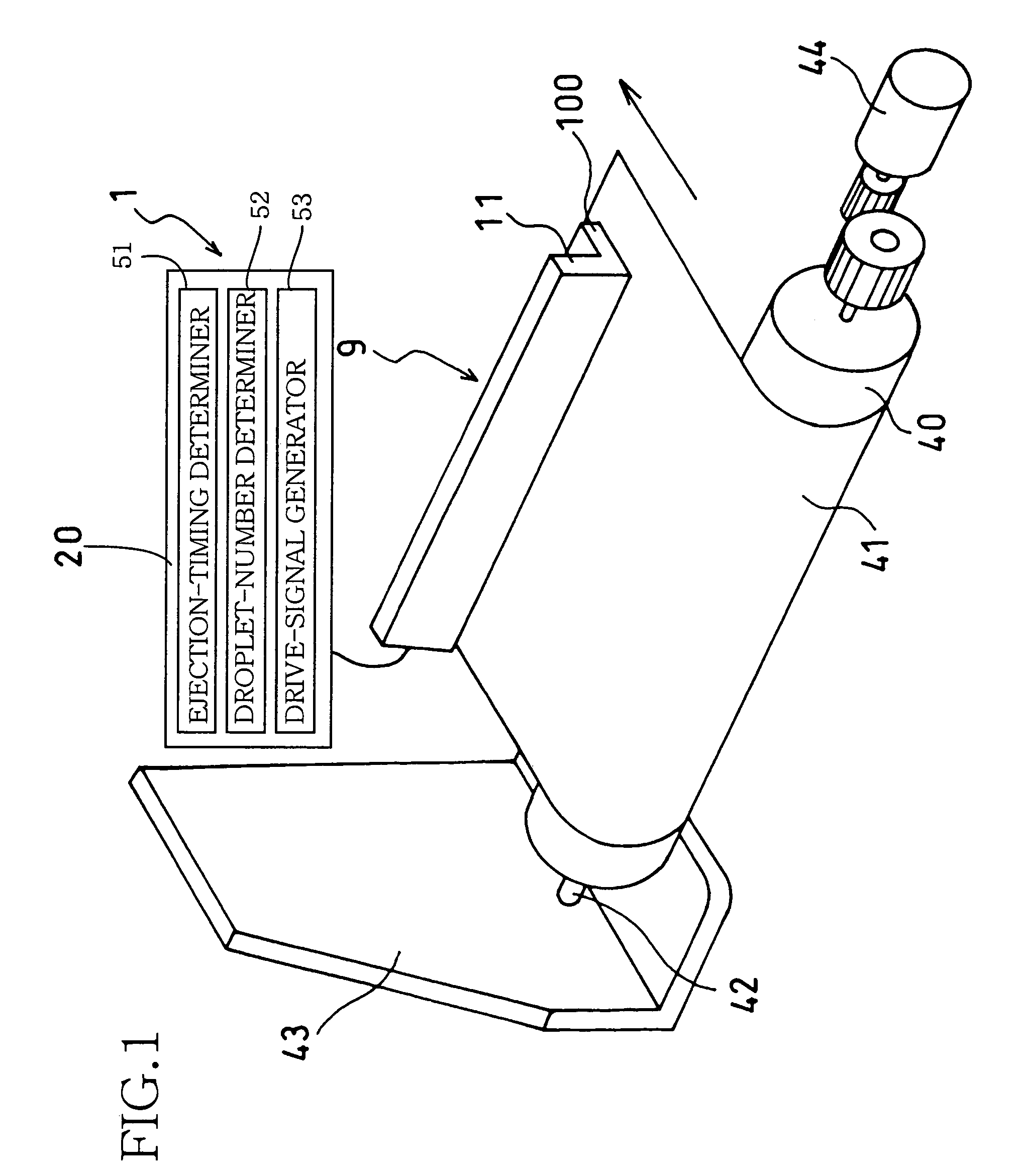
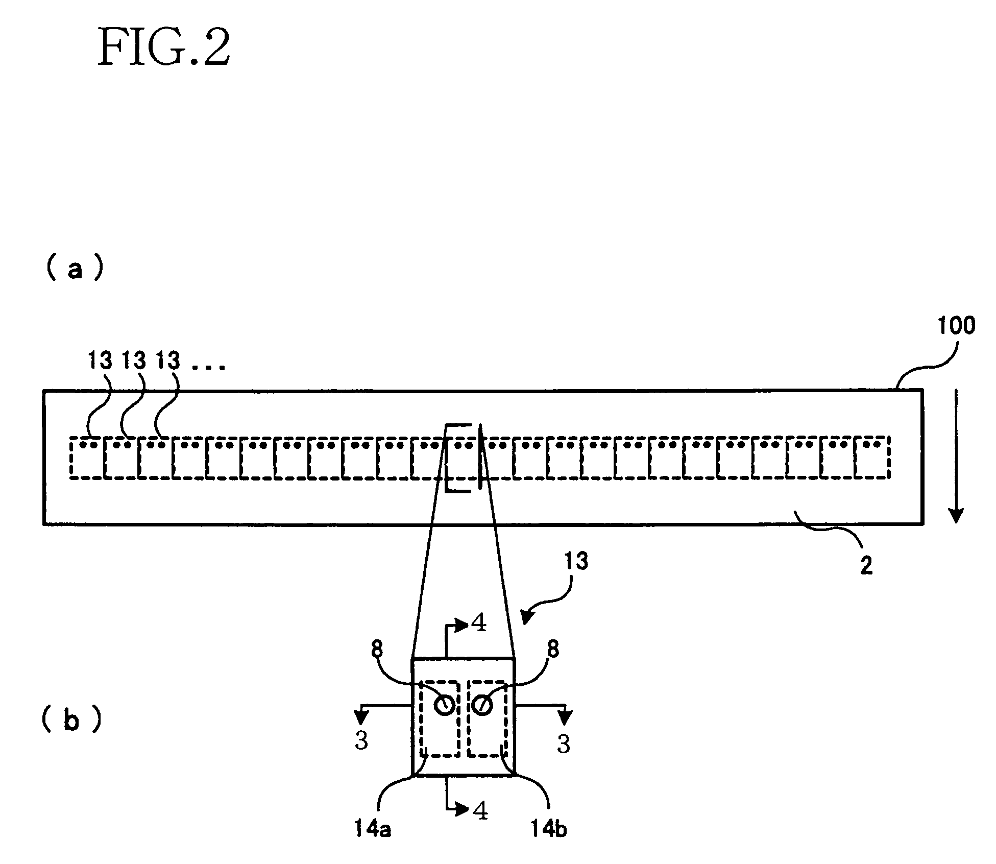
[0052]FIG. 1 is a view schematically illustrating a basic arrangement of an inkjet printer 1 equipped with a droplet ejection device which is constructed according to the invention. As shown in FIG. 1, the inkjet printer 1 includes: a platen roller 40 constituting a feeding device for feeding a receiver medium in the form of a paper sheet 41; a print head 9 arranged to eject ink droplets toward the paper sheet 41 set on the platen roller 40; and a controller 20 for controlling operations of the print head 9 and other components which are incorporated in the inkjet printer 1.

[0053]The platen roller 40 is mounted on a driven shaft 42, and is rotatably attached to a frame 43 through the driven shaft 42. The platen roller 40, together with the driven shaft 42, is rotated by a motor 44. With the rotation of the platen roller 40, the paper sheet 41 supplied from a paper sheet cassette (not shown) is fed at a constant rate in a feed direction indicated by arrow in FIG. 1, so that a printin...

second embodiment

[0103]Further, in the second embodiment, it is possible to form an image with a desired gradation, by simply controlling the number of the ink droplets constituting the united ink droplet, namely, by simply controlling the volume of the united ink droplet.

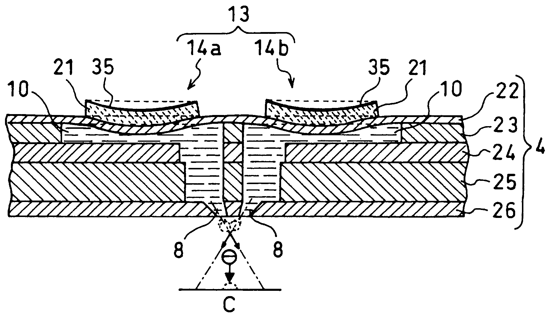
[0104]Referring next to FIGS. 16-27, there will be described a third embodiment of the invention. FIG. 16 is an enlarged plan view of a main body 300 of a print head 309 in this third embodiment. FIG. 17 is a view partly in cross section taken along line 17-17 of FIG. 16. FIG. 18 is a view partly in cross section taken along line 18-18 of FIG. 16. The third embodiment is substantially identical with the first embodiment, except for its print head 309 and controller 320 which will be described below.

[0105]Like the print head 9 in the first embodiment, the print head 309 is of a line type, and has the main body 300 having the ejection face 2 provided by a rectangular flat face. As shown in FIGS. 16-18, the print head 309 has a passag...

third embodiment

[0110]FIG. 19 is a block diagram showing functions of the controller 320 which controls operations of components of the inkjet printer 1 such as the motor 44 and the inkjet head 309. In the present third embodiment, the controller 20 includes an ejection-timing determiner 351, a droplet-number determiner 352 and a drive-signal generator 353. The ejection-timing determiner 351 serves to determine points of time at which the ink droplets are to be ejected from the ink ejecting portions 314a, 314b, such that the droplets ejected from the nozzles 8 of the respective first and second ink ejecting portions 314a, 314b collide to be united before landing on the paper sheet 41. The droplet-number determiner 52 serves to determine numbers of the ink droplets to be ejected from the respective first and second ink ejecting portions 314a, 314b per unit time, such that the united droplet has a desired volume and such that the united droplet is placed at a desired position on the paper sheet 41. T...


PUM


Abstract

A droplet ejection device including: (a) a first ejecting portion capable of ejecting first droplets in a first direction; (b) a second ejecting portion capable of ejecting second droplets in a second direction intersecting the first direction, so that the droplets ejected from the first and second ejecting portions can be united to constitute a united droplet before landing on a receiver medium; and (c) a constituent-droplet-number controller which controls number of the droplets constituting the united droplet such that the united droplet is placed at a variable position on the receiver medium.

Description

[0001]This application is based on Japanese Patent Applications No. 2003-187977 filed in Jun. 30, 2003 and No. 2004-106141 filed in Mar. 31, 2004, the content of which is incorporated hereinto by reference.BACKGROUND OF THE INVENTION[0002]1. Field of the Invention[0003]The present invention relates to a droplet ejection device for ejecting droplets toward a receiver medium.[0004]2. Discussion of Related Art[0005]There is known an inkjet printer which is capable of printing desired patterns of image on a printing medium, by ejecting ink droplets subjected to a gradation control, toward the printing medium through nozzles arranged in a print head of the printer. As the print head of such an inkjet printer, there is known a print head which is equipped with piezoelectric elements adapted to pressurize an ink, for ejecting the pressurized ink in the form of ink droplets. Owing to its accurate controllability and excellent durability, such a print head is widely used. The print head, req...

Claims


Application Information

Patent Timeline
Patent Type & Authority Patents(United States)
IPC IPC(8): B41J29/38B41J2/045B41J2/055B41J2/205B41J2/21H05K3/12
CPCB41J2/04526B41J2/04581B41J2/04588B41J2/04595B41J2/2128B41J2202/06H05K3/1241
Inventor SUGAHARA, HIROTO
Owner BROTHER KOGYO KK
Why Eureka
Try Eureka