Device for retaining a printed circuit board

a technology for retaining devices and printed circuit boards, which is applied in the direction of coupling device connections, coupling parts engagement/disengagement, support structure mounting, etc., can solve the problems of time-consuming and inconvenient fixing of pcbs by screws or push pins, and achieve the effect of quick and convenient retention of printed circuit boards

Active Publication Date: 2008-07-08
AMTRAN TECH CO LTD
View PDF2 Cites 4 Cited by
  • Summary
  • Abstract
  • Description
  • Claims
  • Application Information

AI Technical Summary

Benefits of technology

[0009]It is convenient and time saving by the use of the device for retaining the printed circuit board, and screws, push pins, or other latching elements are not required. Also, since screws, push pins are not required, it is not necessary to provide a portion of surface area of the PCB for fixing, thus increasing utilizable surface area of the PCB and effectively reducing the manufacturing cost. The structure of the device also eliminate the problem of scraping the PCB when screwing screws. By grouding the device, electromagnetic interference (EMI) shielding effect is also provided. Furthurmore, the device can be used for a seat of a button to be fixed thereon, thus a button can be presses to contact a swich on the PCB.

Problems solved by technology

Fixing the PCB by the use of screws or push pins is time consuming and inconvenient.

Method used


Image

  • Device for retaining a printed circuit board
  • Device for retaining a printed circuit board
  • Device for retaining a printed circuit board

Examples


Embodiment Construction

[0018]The present invention is provided to fixing a printed circuit board (PCB) without screws, push pins, or other types of latching elements. When the PCB assembled to or disassembled from a electronic device, the PCB can be removed or fixed quickly, thereby improving the working efficiency.

[0019]In order to make the aforementioned and other objectives, features and advantages of the present invention comprehensible, preferred embodiments accompanied with figures are described in detail below.

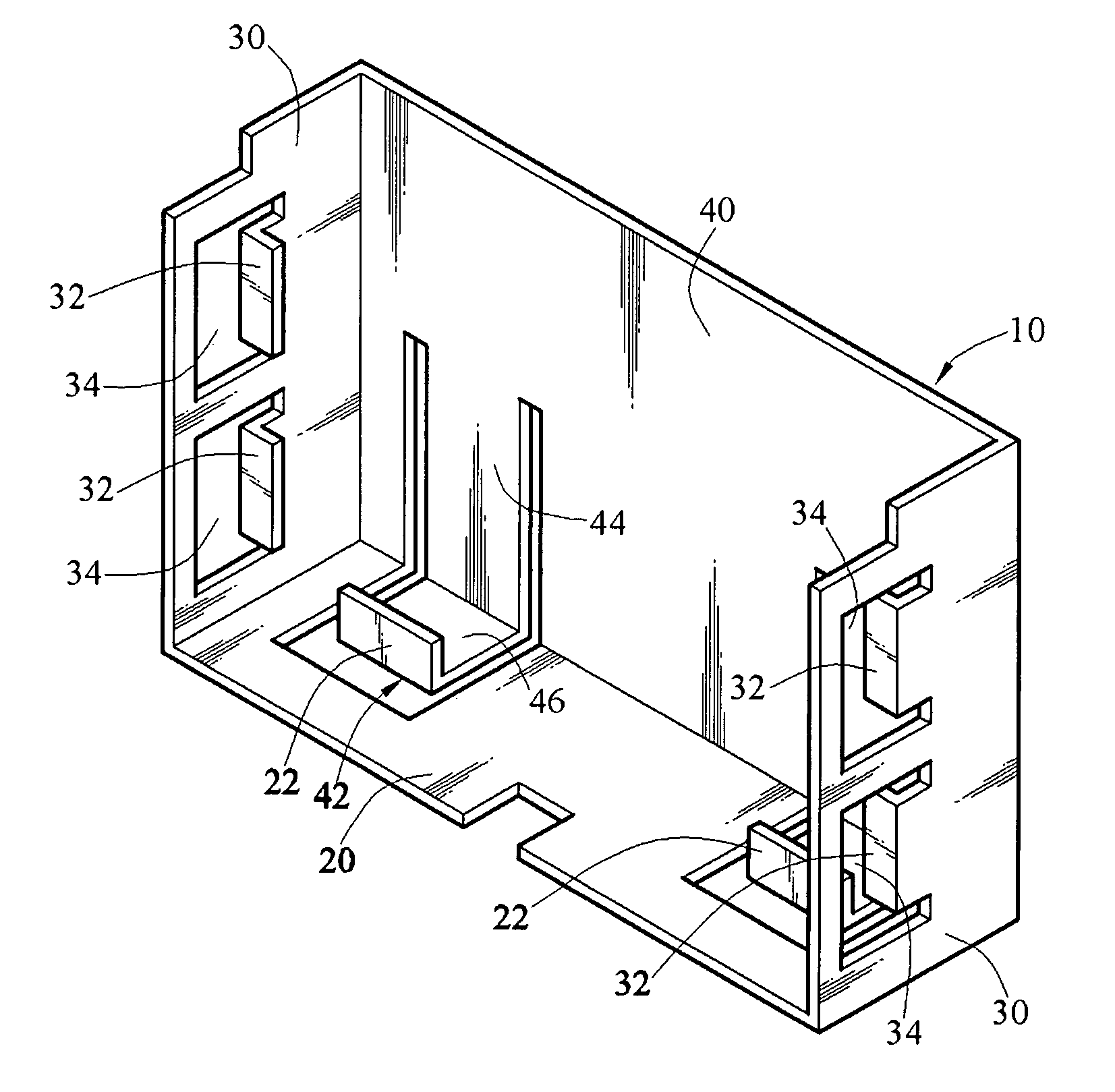
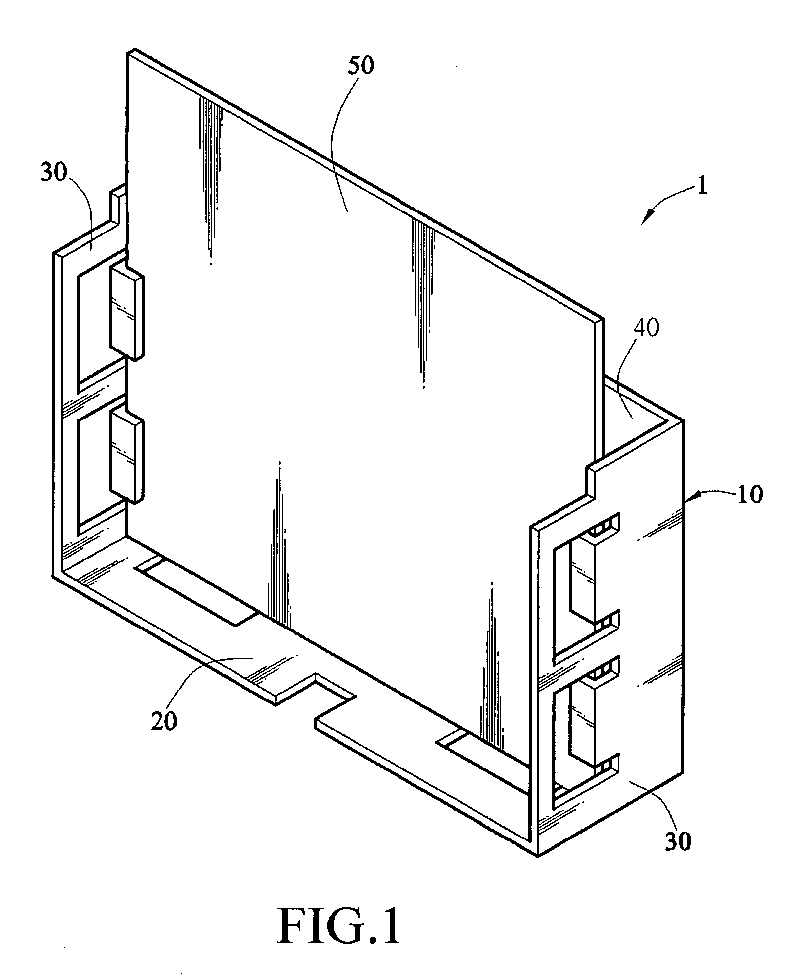
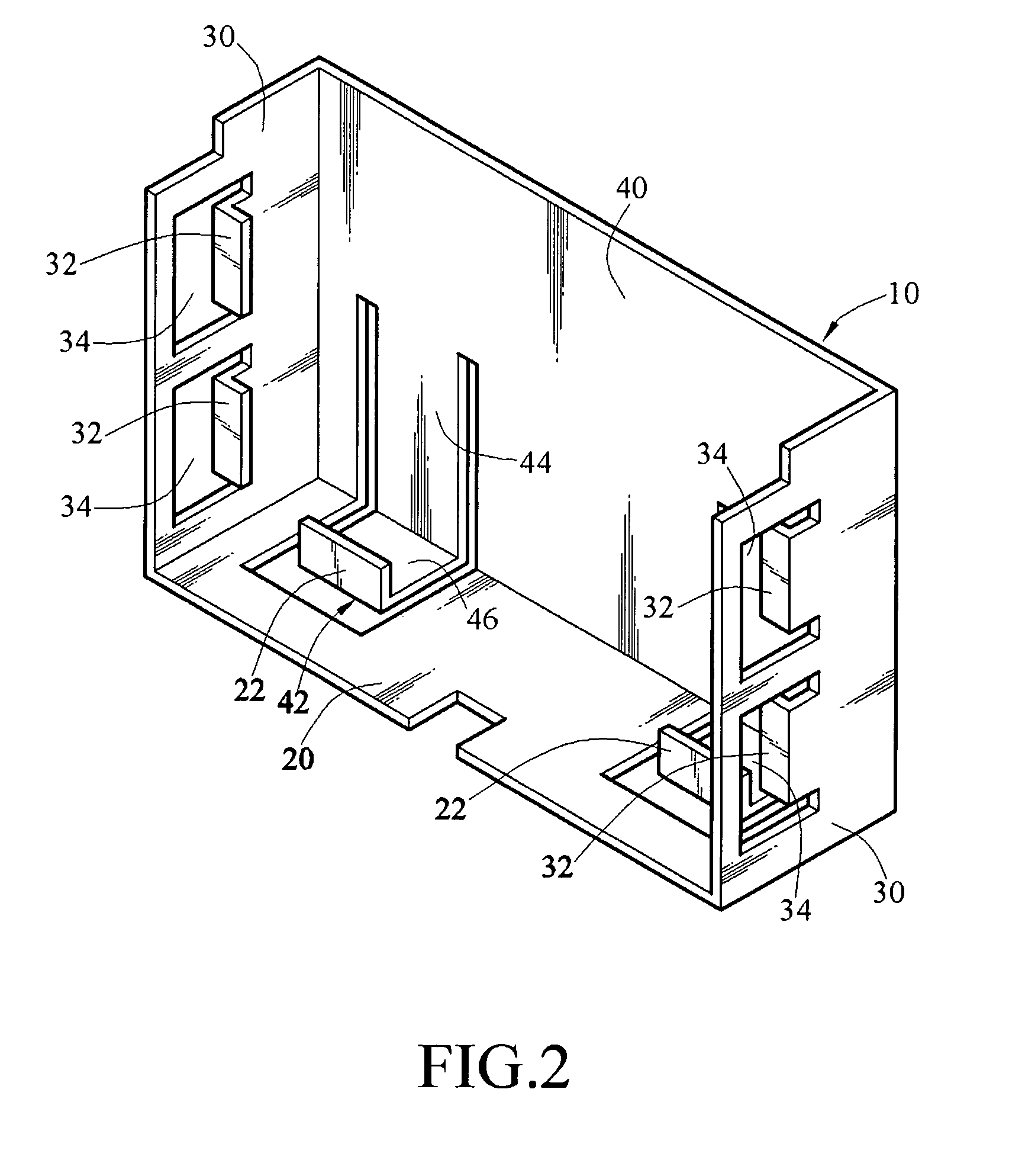
[0020]Referring to FIG. 1, a device 1 for retaining a printed circuit board 50 (PCB) of a first embodiment of the present invention is provided, which includes a fixing frame 10 for fixing the PCB 50 therein.

[0021]The fixing frame 10 is made of metal and has a first side plate 20, two second side plates 30, and a third side plate 40. The two second side plates 30 extend from two opposite side edges of the first side plate 20, so that the fixing frame 10 embraces a semi-open region. The third ...


PUM


Abstract

A device for retaining a printed circuit board is provided, which includes a first side plate and two second side plates. The first has at least one first rib perpendicularly protruding therefrom, each of the second side plate has at least one second rib perpendicularly protruding therefrom. The second ribs of the two second side plate are located in a same plane, and the plane that the second ribs of the two second side plates are located is spaced from that the first rib is located. When a printed circuit board (PCB) is placed in the device, the first rib presses against one side surface of the PCB, and the second rib press against the other side surface of the PCB, so that the PCB is retained in the device.

Description

CROSS-REFERENCE TO RELATED APPLICATIONS[0001]This non-provisional application claims priority under 35 U.S.C. §119(a) on Patent Application No(s). 095218850 filed in Taiwan, R.O.C. on Oct. 25, 2006, the entire contents of which are hereby incorporated by reference.BACKGROUND OF THE INVENTION[0002]1. Field of the Invention[0003]The present invention relates to a circuit board clip apparatus, and more particularly to a clip apparatus using a frame to clip a printed circuit board (PCB).[0004]2. Related Art[0005]Fixing a printed circuit board (PCB) into a housing of an electronic device in the art is achieved by the use of screws or push pins. As for a small PCB, a plurality of fixing holes are formed in the PCB near the the edges of the PCB. Then, the PCB is placed onto the housing of an electronic device that the PCB is going to be fixed onto, and the fixing holes of the PCB and the screw holes of the housing are aligned. Screws are then passed through the fixing holes and screwed int...

Claims


Application Information

Patent Timeline
Patent Type & Authority Patents(United States)
IPC IPC(8): H01R13/62
CPCH05K7/1417
Inventor LIN, HUANG-PIN
Owner AMTRAN TECH CO LTD
Why Eureka
Try Eureka