Recording tape cartridge

a technology of recording tape and cartridge, which is applied in the field of recording tape cartridge, can solve the problems of easy dus

Inactive Publication Date: 2008-08-05
FUJIFILM HLDG CORP +1
View PDF28 Cites 5 Cited by
  • Summary
  • Abstract
  • Description
  • Claims
  • Application Information

AI Technical Summary

Benefits of technology

[0013]In a case in which this concave portion is provided, the concave portion which engages with the guide wall portion is formed in the braking member. Therefore, a maze-like structure can be formed by the guide wall portion and the concave portion. Accordingly, entry of dust or the like in from the pass-through hole can further be suppressed thereby. Thus, adhesion of dust or the like to the recording tape can be prevented.

Problems solved by technology

If the recording tape cartridge is loaded into a drive device in this state, not only will recording and playback not be possible, but also, breakage of the recording tape cartridge or malfunctioning of the drive device may be caused.
Moreover, there is also the problem that it is easy for dust and the like to enter in from the pass-through hole 114A.

Method used


Image

  • Recording tape cartridge
  • Recording tape cartridge
  • Recording tape cartridge

Examples


Embodiment Construction

[0024]Here, a recording tape cartridge relating to an embodiment of the present invention (which will be called “magnetic tape cartridge” hereinafter) will be summarily described.

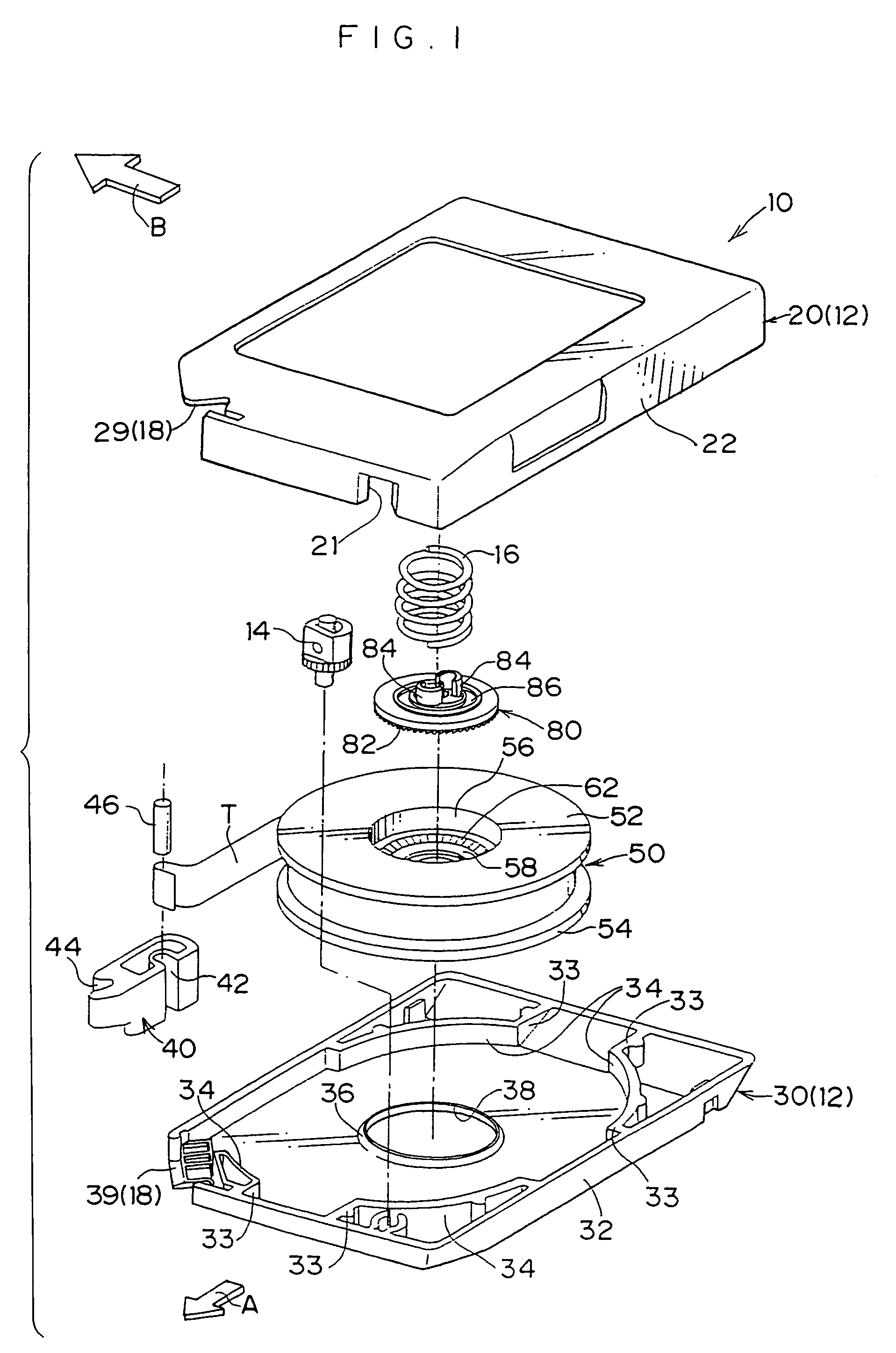
[0025]For convenience of explanation, the direction of loading a magnetic tape cartridge 10 shown in FIG. 1 into an unillustrated drive device (i.e., the direction of arrow A) will be called the front direction, and the direction of arrow B will be called the downward direction. Front, back, left, right, up and down will be expressed by using, as a reference, a case of looking in the direction of arrow A.

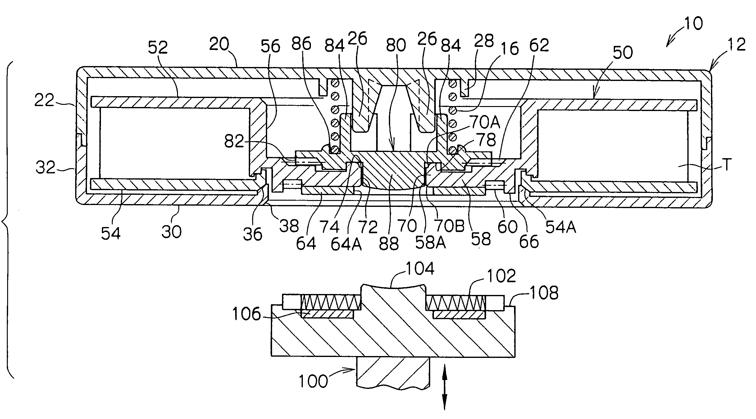
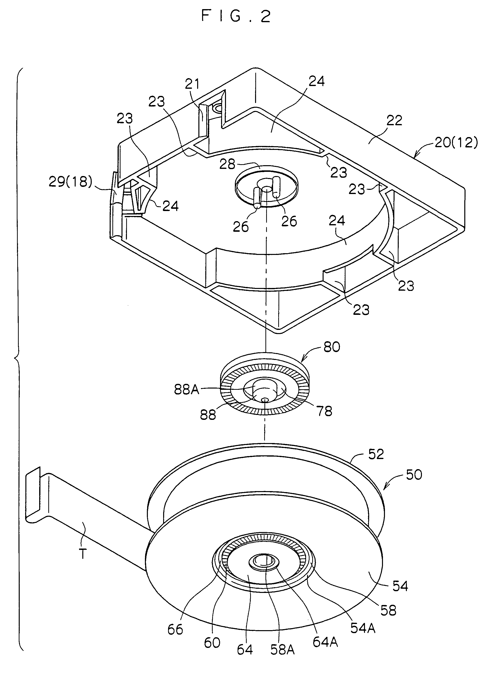
[0026]As shown in FIGS. 1 through 5B, the magnetic tape cartridge 10 has a case 12. The case 12 has an upper case 20 and a lower case 30, which are formed of a synthetic resin and joined together by ultrasonic welding or the like in a state in which peripheral walls 22, 32 thereof abut one another. Play restricting walls 24, 34 stand erect at the inner surfaces of the upper case 20 and the lower case 30. Ea...


PUM

PropertyMeasurementUnit
diameteraaaaaaaaaa
lengthaaaaaaaaaa
lengthaaaaaaaaaa

Abstract

A recording tape cartridge with a reel in a case, a hollow cylinder shaped hub and a recording tape wound around the hub has a braking member provided so as to be unrotatable within the case. The braking member can be set at a locking position, at which the braking member engages with an engaging portion formed at a top surface of a floor of the hub and impedes rotation of the reel, and a rotation permitting position, at which engagement with the engaging portion is cancelled due to the braking member moving away from the top surface of the floor of the hub due to pushing-up of an operation portion which is inserted through a pass-through hole of the hub. A guide wall, which extends toward the braking member and always opposes a side surface of the operation portion, is formed at a peripheral edge of the hole.

Description

CROSS-REFERENCE TO RELATED APPLICATION [0001]This application claims priority under 35 USC 119 from Japanese Patent Application No. 2003-284296, the disclosure of which is incorporated by reference herein.BACKGROUND OF THE INVENTION[0002]1. Technical Field[0003]The present invention relates to a recording tape cartridge which accommodates, within a case, a single reel on which is wound a recording tape such as a magnetic tape or the like used as a recording / playback medium mainly for computers or the like.[0004]2. Description of the Related Art[0005]Conventionally, recording tape cartridges (magnetic tape cartridges) have been known in which a magnetic tape, which is used as a data recording / playback medium for computers or the like, is wound on a single reel, and the reel is accommodated within a case formed of a synthetic resin. Such a recording tape cartridge is equipped with a braking means so that the reel does not rotate within the case when the recording tape cartridge is not...

Claims


Application Information

Patent Timeline
Patent Type & Authority Patents(United States)
IPC IPC(8): G11B23/107G11B23/04G11B23/087
CPCG11B23/107G11B23/043
Inventor HIRAGUCHI, KAZUO
Owner FUJIFILM HLDG CORP
Why Eureka
Try Eureka