Recoil starter

a starter and coil technology, applied in the direction of engine starters, muscle operated starters, machines/engines, etc., can solve the problems of no particular dustproof measure adopted to positively prevent such drawbacks, the dust entering the starter case, and the rope being pulled out of the rope reel by pulling operation is worsened, so as to improve the dustproof effect of the bearing portion, simplify the configuration, and facilitate the use of the dust cover

Active Publication Date: 2008-12-02
STARTING IND CO LTD
View PDF20 Cites 5 Cited by
  • Summary
  • Abstract
  • Description
  • Claims
  • Application Information

AI Technical Summary

Benefits of technology

[0008]In order to solve the above problems in the prior art, the present invention proposes an improved structure of the recoil starter. It is an object of the present invention to provide a recoil starter whose dustproof property is excellent and whose operation is stable, capable of positively preventing the drawbacks of a defective operation caused due to adhesion of dust onto constituent members of main mechanism portions housed and arranged in a starter case, i.e., a recoil spring, a rope reel, a damper spring, etc. by preventing the adhesion of dust to these members.
[0013]According to the first aspect of the invention, the bearing portion constructed integrally with the starter case to support turnably the other end of the cam member when the bearing portion is fixed to the starter case is provided, and also the dust cover constituting the sealed space in which the main mechanism portions are housed so as to project only the cam claws that engage with the ratchet mechanism of the cam member to the outside is provided. Therefore, members of the main mechanism portions such as the rope reel, the recoil spring, the damper spring, the portion of the cam member to which the damper spring is fitted, etc. are housed and arranged in the sealed space that is covered with the dust cover being integrated with the starter case. As a result, generation of the drawbacks such as the wrong return of the recoil rope, which has been extracted by the pulling operation of the rope reel, due to the adhesion of dust onto the recoil spring and the recoil rope, for example, and the like can be avoided. Also, since the bearing portion of the dust cover bears / supports the other end of the cam member, stable turning / supporting of the cam member can be attained and also provision of another member for supporting the cam member is not needed. Thus, a simplification of configuration can be achieved.
[0014]According to the second aspect of the invention, the cam member is constructed by the cam base on which the damper spring is fitted, and by the cam plate having cam claws that engage with the ratchet mechanism. Therefore, the cam base used in fitting the damper spring of the cam member is housed in the space covered with the dust cover, nevertheless the cam plate with the cam claws of the cam member can be exposed from the space covered with the dust cover. As a result, an engaging operation between the cam claws of the cam member and the ratchet mechanism can be carried out without hindrance. Also, the bearing / supporting of the cam member consisting of the cam base and the cam plate by using the dust cover can be facilitated.
[0015]According to the third aspect of the invention, the dust seal is fitted to the bearing portion, which supports turnably the cam member, of the dust cover. As a result, a dustproof effect of the bearing portion can be improved.
[0016]According to the fourth aspect of the invention, the engaging portions at both ends of the damper spring are bent like a U-shape respectively. As a result, the engagement of both ends of the damper spring with the rope reel and the cam member can be facilitated, and also a reduction in fitting cost of the damper spring can be attained.

Problems solved by technology

As a result, dust enters into the starter case through the opening portion of the starter case.
Dust that enter into the starter case adhere to the constituent members of the main mechanism portions such as the rope reel, the recoil spring, the damper spring, etc., and cause such drawbacks that returning of the rope being pulled out from the rope reel by a pulling operation is worsened, and the like.
However, no particular dustproof measure has been adopted to positively prevent such drawbacks.

Method used


Image

  • Recoil starter
  • Recoil starter
  • Recoil starter

Examples


Embodiment Construction

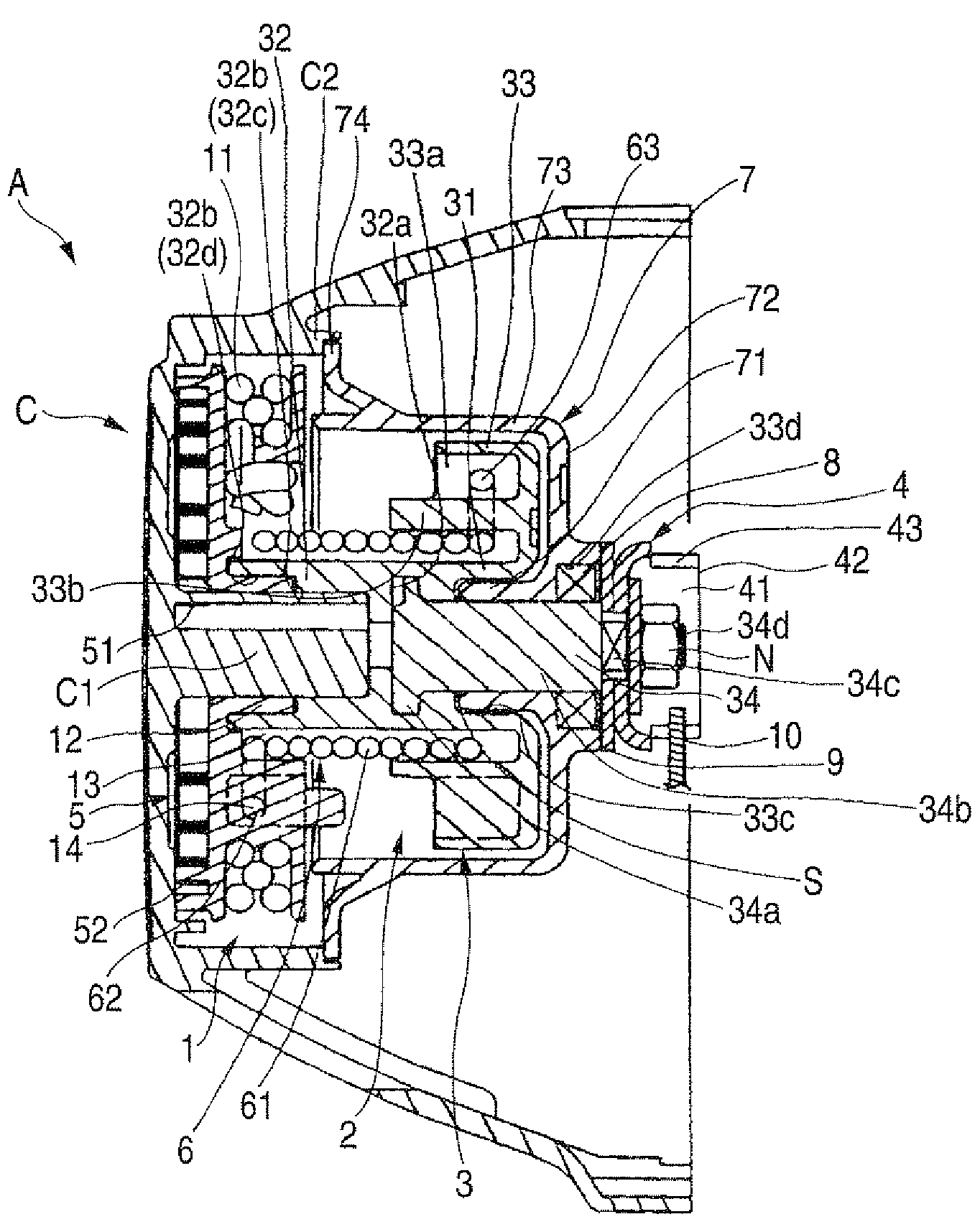
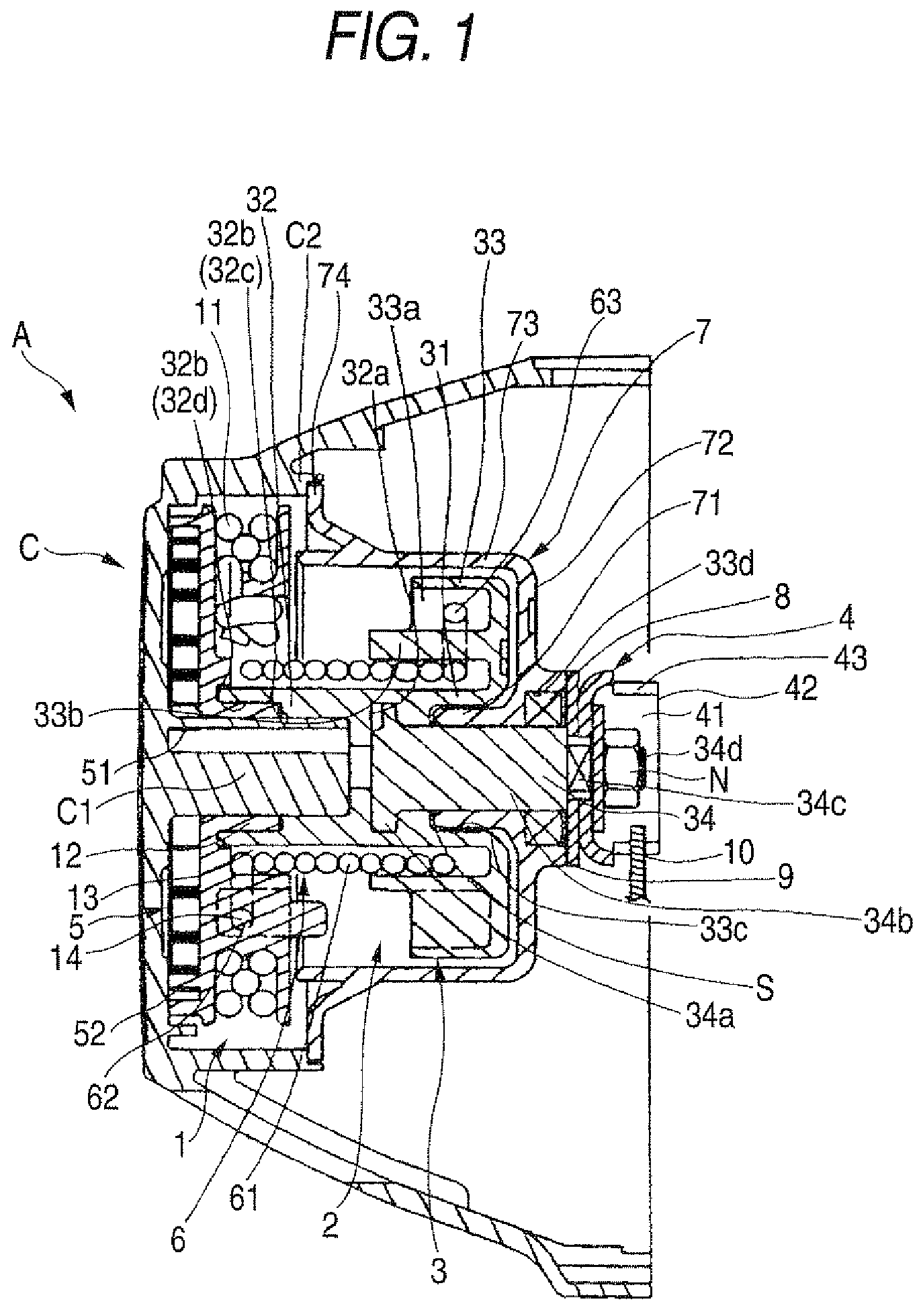
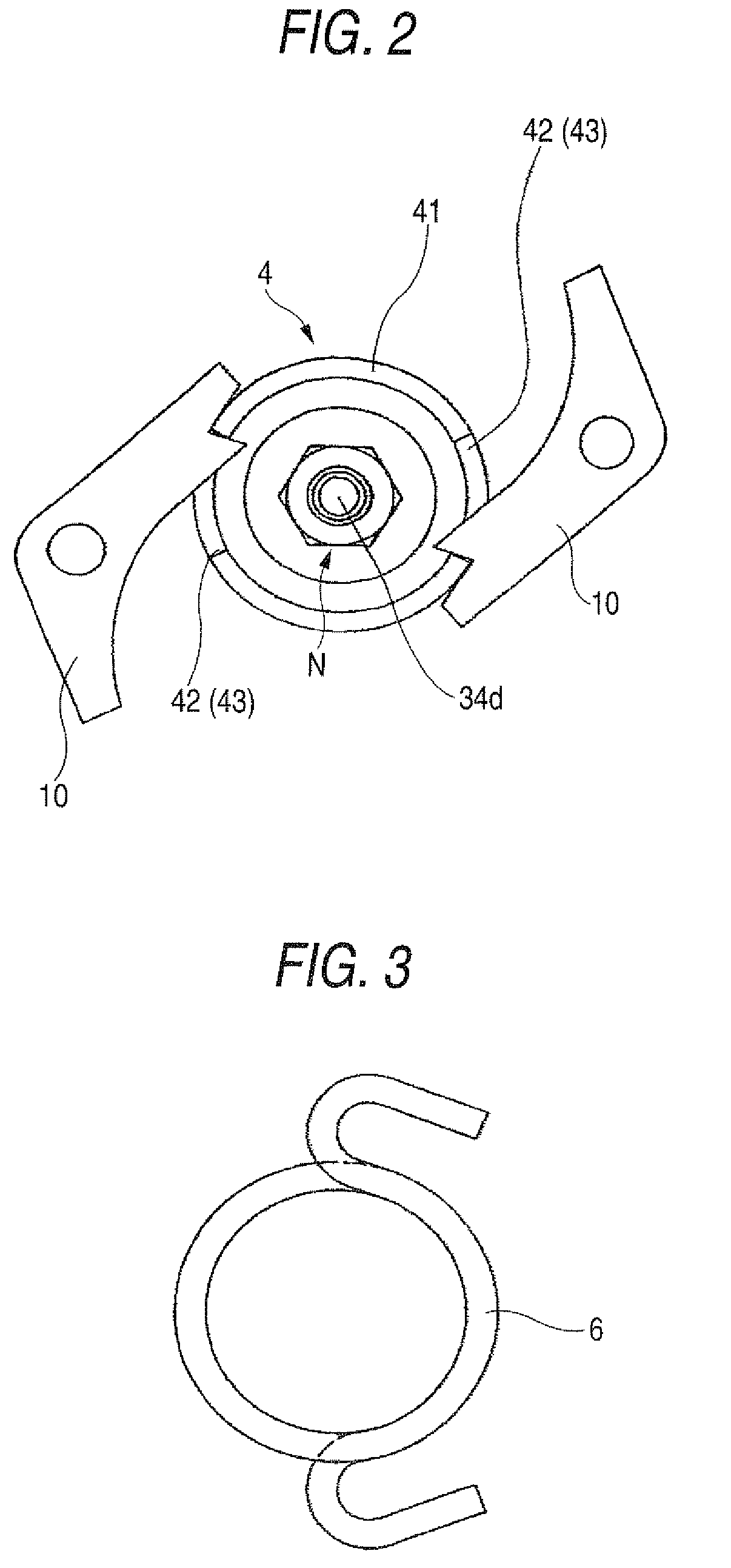
[0021]A characteristic feature of the present invention is that, in a recoil starter A for starting an engine by transferring a turning force of a rope reel 1 to a cam member 2 via an elasticity of a damper spring 6, and then transferring the turning of the cam member 2 to the engine side via a ratchet mechanism 10, constituent members of main mechanism portions except structural portions being inevitably exposed, such as cam claws 43 of the recoil starter A, etc. are housed in a sealed space covered with a dust cover 7 that is formed integrally with a starter case C in such a way that no dust adheres to the constituent members of the main mechanism portions such as a recoil spring 5, the rope reel 1, the damper spring 6, and the like.

[0022]Then, a more concrete embodiment will be explained hereinafter.

[0023]The recoil starter A of the present invention is shown in FIG. 1. First, an outline of the recoil starter will be described hereunder. The rope reel 1 is arranged turnably in th...


PUM


Abstract

A recoil starter includes: a rope reel on which a recoil rope, one end of which is held on an outside of a starter case, is wound and which is fitted turnably on a reel pivot formed on an inside of the starter case; a recoil spring that turns and energizes the rope reel in a direction along which the recoil rope is rewound; a cam member one end of which is fitted turnably onto the reel pivot to oppose to the rope reel and which transfers a turning to an engine side via a ratchet mechanism; and a coil spring-like damper spring both ends of which are engaged with the rope reel and the cam member respectively; a bearing portion that supports turnably the cam member; and a dust cover provided integrally with the starter case.

Description

BACKGROUND OF THE INVENTION[0001]1. Field of the Invention[0002]The present invention relates to a recoil starter for starting an engine by pulling out one end, which is held on the outside of a starter case, of a recoil rope wound on a rope reel so as to turn the rope reel, then transferring a turning of the rope reel to a cam member via a damper spring, and then transferring a turning of the cam member to the engine side via a ratchet mechanism.[0003]2. Background Art[0004]An existing recoil starter is disclosed in JP-A-2006-132519. The recoil starter is constructed to start the engine by interposing the damper spring wound like a coil spring between the rope reel and the cam member. Both members are coupled elastically via the damper spring in the turning direction such that, when the recoil rope is pulled out, the turning of the rope reel is transferred to the cam member via the damper spring and then the turning of this cam member is transferred to the engine side via the ratch...

Claims


Application Information

Patent Timeline
Patent Type & Authority Patents(United States)
IPC IPC(8): F02N3/02
CPCF02N3/02F02N5/02F02N15/027F02N2250/08
Inventor FUJITA, HIROTOSHITOHYAMA, ISAO
Owner STARTING IND CO LTD
Why Eureka
Try Eureka