Manufacturing method of optical sheets for display

a manufacturing method and technology for display, applied in the field of manufacturing methods of optical sheets for display, can solve the problems of high power consumption of liquid crystal display units, obstacles to extending battery time, limit to available power, etc., and achieve the effects of reducing labor costs, reducing material costs, and reducing the number of operations

Inactive Publication Date: 2009-03-26
FUJIFILM CORP
View PDF12 Cites 5 Cited by
  • Summary
  • Abstract
  • Description
  • Claims
  • Application Information

AI Technical Summary

Benefits of technology

[0023]The integration of optical sheets into a compound optical sheet according to the present invention eliminates the need for protective sheets for lens sheets, resulting in reduced material costs. Also, this reduces the number of operations needed to mount members during backlight assembly, resulting in reduced labor costs. Furthermore, it prevents dust adhesion caused by separation electrification which occurs when the protective sheets are removed.
[0024]Also, the present invention eliminates the need to purchase a lens sheet and light diffusion sheet separately. This reduces management costs for distribution and storage. Besides, the lens sheet and light diffusion sheet, which are soft and flabby, have poor handleability when handled singly, but when they are combined by the method of the present invention, the hardness of their outer edges are increased, resulting in increased working efficiency.

Problems solved by technology

On portable notebook computers and portable phones equipped with a color liquid crystal display unit, portable liquid crystal television sets, player-equipped liquid crystal displays, and the like, high power consumption of the liquid crystal display units is one of the obstacles to extending battery time.
However, with the above-described products which use a liquid crystal display unit, there is a limit to available power because of the need to ensure extended use and there is only so much that the quantity of light from the light source can be increased.
However, it is not desirable if an attempt to reduce the power consumption of the backlight results in reduced luminance of the backlight because then it will become difficult to see the liquid crystal display.

Method used


Image

  • Manufacturing method of optical sheets for display
  • Manufacturing method of optical sheets for display
  • Manufacturing method of optical sheets for display

Examples


example 1 of

PRODUCTION LINE FOR OPTICAL SHEETS FOR DISPLAYS

[0117]Next, an example of a production line for optical sheets for displays will be described. The production line described below is commonly applicable to the optical sheets 10 to 60 for displays. For convenience of explanation, however, it is applied here to an optical sheet for displays consisting of four laminated layers (first embodiment).

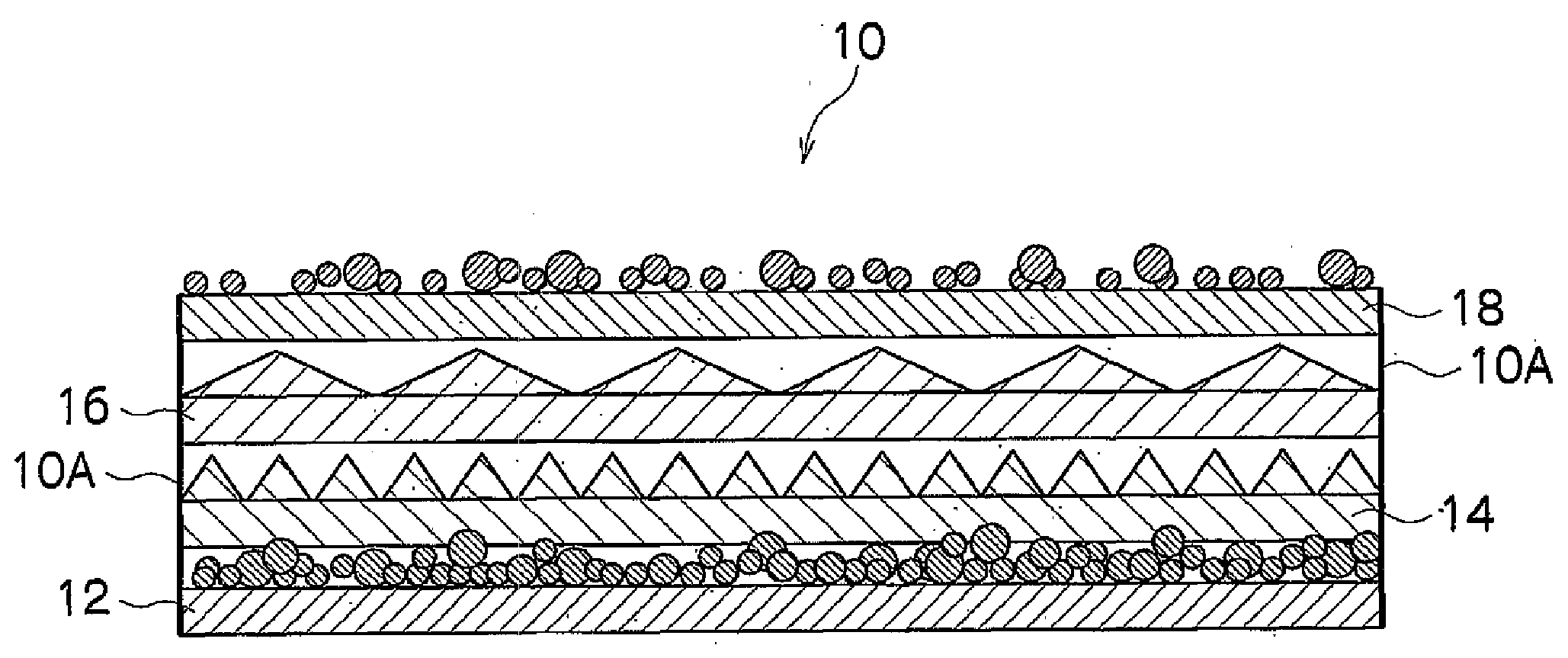
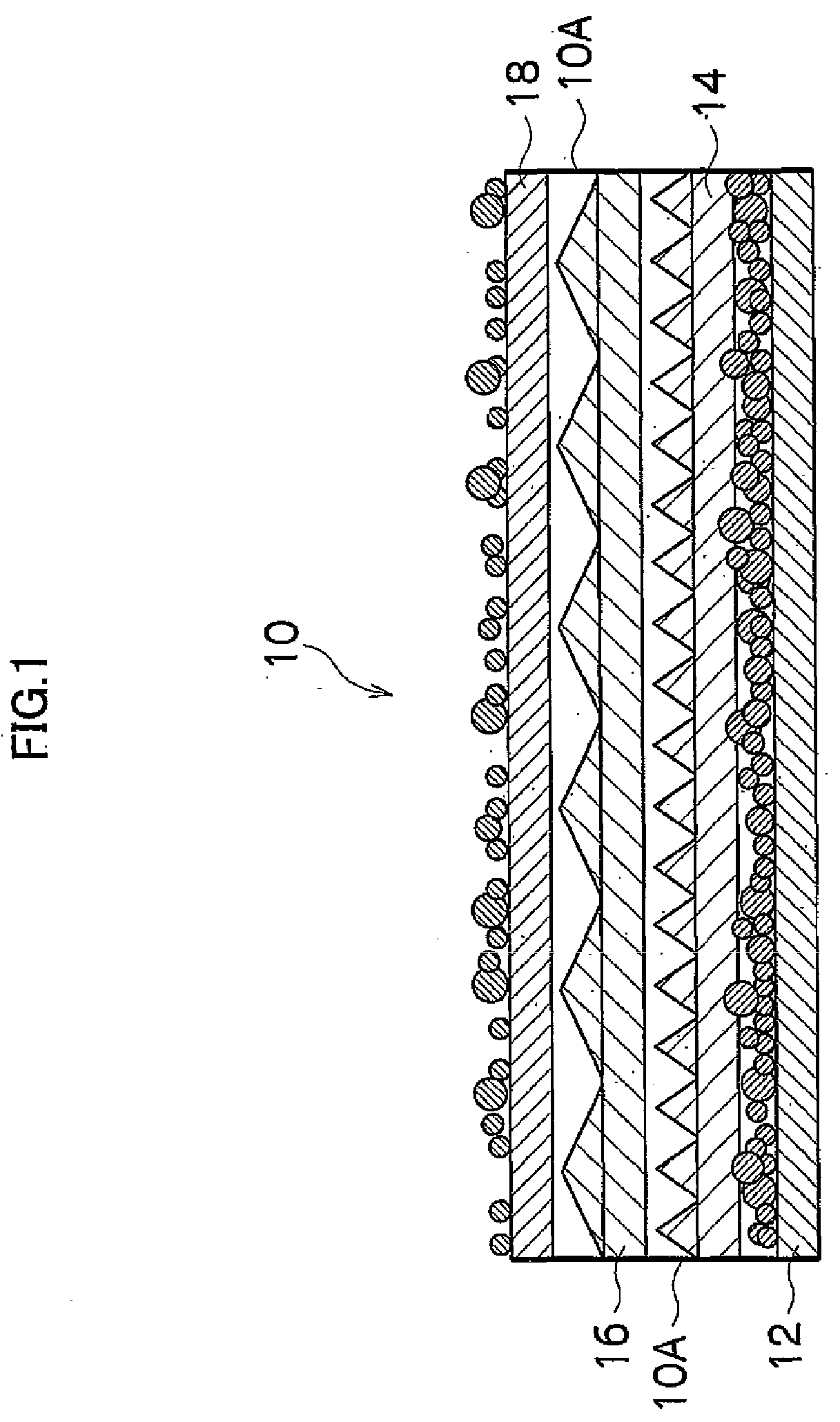
[0118]FIG. 13 is a block diagram of a production line 11 for optical sheets for displays. Rolls 12B, 14B, 16B, and 18B on the left side of FIG. 13 are rolls of the first diffusion sheet 12, first prism sheet 14, second prism sheet 16, and second diffusion sheet 18 in FIG. 1, respectively.

[0119]The rolls 12B, 14B, 16B, and 18B are supported about rotating shafts of respective feeding means (not shown) so that the first diffusion sheet 12, first prism sheet 14, second prism sheet 16, and second diffusion sheet 18 can be fed from the rolls 12B, 14B, 161B, and 188B, respectively, at approximately the...

example 2 of

PRODUCTION LINE FOR OPTICAL SHEETS FOR DISPLAYS

[0136]FIG. 14 is a block diagram showing a production line 51 for optical sheets for displays according to another embodiment. Incidentally, components identical with or similar to those of the production line 11 for optical sheets for displays in FIG. 13 are denoted by the same reference numerals as the corresponding components in FIG. 13, and detailed description thereof will be omitted.

[0137]The production line 51 for optical sheets for displays in FIG. 14 employs laser heads 72, 74, and 76 and press 48 (press unit) (see FIG. 14) instead of the laser head 24 of the production line 11 for optical sheets for displays in FIG. 13. The laser heads 72, 74, and 76 are installed downstream of press rollers (guide rollers G).

[0138]The laser heads 72, 74, and 76 are used to fuse two or more laminated sheets together. Specifically, the laser head 72 fuses the first diffusion sheet 12 and first prism sheet 14 together, the laser head 74 fuses th...

example 3 of

PRODUCTION LINE FOR OPTICAL SHEETS FOR DISPLAYS

[0142]Next, still another example of the production line for optical sheets for displays will be described. FIG. 15 is a block diagram of a production line 61 for optical sheets for displays according to another embodiment. Incidentally, components identical with or similar to those of the production line 11 for optical sheets for displays in FIG. 13 and production line 51 for optical sheets for displays in FIG. 14 are denoted by the same reference numerals as the corresponding components in FIGS. 13 and 14, and detailed description thereof will be omitted.

[0143]The production line 61 for optical sheets for displays in FIG. 15 employs one laser head 78 instead of the three laser heads 72, 74, and 76 of the display optical sheets production line 51 in FIG. 14. The laser head 78 is installed downstream of press rollers (guide rollers G).

[0144]The laser head 78 is used to fuse two or more laminated sheets together. Specifically, the laser ...


PUM

PropertyMeasurementUnit
bead diameteraaaaaaaaaa
grain sizeaaaaaaaaaa

Abstract

The present invention provides a fabrication method which promotes adhesion of sheet materials when bonding a plurality of optical sheets into a compound sheet and provides a manufacturing method of optical sheets suitable for liquid crystal display units and the like. A manufacturing method according to one aspect of the present invention includes a lamination step of laminating a plurality of optical sheets; and a bonding step of irradiating at least one or more spots on a laminate of the optical sheets prepared in the lamination step with a laser beam from one side of the laminate and thereby bonding the irradiated spots to obtain a compound optical sheet in which the plurality of optical sheets are integrated. Preferably, the method further includes a step of forming a photothermal conversion layer from a light absorber between the optical sheets to be fused. Incidentally, ultrasonic welding may be used instead of, or in combination with, laser welding.

Description

TECHNICAL FIELD[0001]The present invention relates to a manufacturing method of optical sheets for displays. More particularly, it relates to a fabrication technique which makes it easy to assemble and handle display members used for liquid crystal display units and the like and which is suitable for manufacturing inexpensive high-performance optical sheets for displays.BACKGROUND ART[0002]On portable notebook computers and portable phones equipped with a color liquid crystal display unit, portable liquid crystal television sets, player-equipped liquid crystal displays, and the like, high power consumption of the liquid crystal display units is one of the obstacles to extending battery time. These liquid crystal display units are mainly a backlight type which involves making a liquid crystal layer emit light by illuminating it from behind. In such backlight-type liquid crystal display units, a backlight unit is installed under the liquid crystal layer.[0003]Generally, a backlight un...

Claims


Application Information

Patent Timeline
Patent Type & Authority Applications(United States)
IPC IPC(8): B32B37/06B32B38/04
CPCB29C35/10Y10T156/1052B29C39/18B29C59/046B29C65/02B29C65/08B29C65/16B29C65/1616B29C65/1635B29C65/1654B29C65/1677B29C65/168B29C65/1687B29C66/1122B29C66/21B29C66/24B29C66/43B29C66/81463B29C66/832B29C66/83411B29C66/83413B29C66/929B29C66/939B29C66/949B29K2001/12B29K2067/00B29L2009/00B29L2011/00G02B6/0051G02B6/0053G02B6/0065G02F1/1303G02F1/1335G02F1/133504G02F1/133526G02F2001/133607G02F2202/28B29C39/148B29C66/93431B29C66/919B29C66/9161B29C66/8322B29C65/1658B29C65/086B29C65/00B29C66/242B29C66/24244B29C66/71B29C66/73921B29C66/8242B29C66/863B29K2995/0027G02F1/133607B29K2079/08B29K2077/10B29K2077/00B29K2069/00B29K2067/003B29K2033/12B29K2033/08B29K2031/04B29K2027/08B29K2027/06B29K2025/06B29K2023/12B29K2023/06B29K2023/00G02B5/02
Inventor ENDO, KEISUKETAKEDA, AKIHIKO
Owner FUJIFILM CORP
Why Eureka
Try Eureka