Hydrodynamic brush seal

a brush seal and hydrodynamic technology, applied in the field of brushes, can solve the problems of excessive engine vibration, carryover effect, and potential increase of engine vibration

Active Publication Date: 2008-08-12
SIEMENS ENERGY INC
View PDF22 Cites 102 Cited by
  • Summary
  • Abstract
  • Description
  • Claims
  • Application Information

AI Technical Summary

Benefits of technology

[0013]A hybrid brush seal is provided which is generally similar to the one disclosed in my prior U.S. Pat. No. 6,428,009, but which overcomes the tendency of the shoes to roll over under the application of a pressure load.
[0015]In alternative embodiments, one or more bundles or seal bristles are mounted at one end to either the rotor or the stator, and their opposite end extends toward one or more shoes located proximate the other of the rotor or stator. A spring element is connected between the shoes and the rotor or stator which is flexible in the radial direction, but axially stiff. The spring element functions to assist in preventing roll over of the shoes with respect to the rotor or stator where it is located, thus maintaining an effective seal under pressure load. In one embodiment, stops are provided to limit the extent of radial motion of the shoe with respect to the rotor or stator. It is contemplated that the ends of the seal bristles proximate the shoes can be either connected to the shoes such as by welding or other means of attachment, or spaced from the shoes. In either case, the seal bristles act as a secondary seal between the rotor and stator in combination with the shoes.
[0017]The advantages of the hybrid brush seal of this invention are many. It has the same sealing characteristics of existing brush seals, but will never change in performance due to bristle wear. The brush seal backing plate can be moved further outboard of the I.D. because the shoe prevents the bristles from bending over in high pressure applications. Each shoe may have a certain amount of interference with the rotor or stator prior to rotation. Thus, the seal can be slightly off center during assembly but once rotation begins, each pad will lift-off. Hence, tight tolerances can be relaxed.
[0018]The hybrid seal of this invention can be utilized in all seal applications, including labyrinth, brush and carbon. The robust design eliminates the careful handling now required of carbon seals utilized in lube system compartments. This seal may allow the engine designer to utilize less parts in the assembly as this seal will permit “blind” assemblies to occur.

Problems solved by technology

In addition to increased leakage if clearances are not maintained, such as during a high-G maneuver, there is the potential for increases in engine vibration.
Straight-thru labyrinth seals (FIG. 1A) are the most sensitive to clearance changes, with large clearances resulting in a carryover effect.
Other problems associated with labyrinth seals arise from heat generation due to knife edge to seal land rub, debris from hardcoated knife edges or seal lands being carried through engine passages, and excessive engine vibration.
When seal teeth rub against seal lands, it is possible to generate large amounts of heat.
This heat may result in reduced material strength and may even cause destruction of the seal if heat conducted to the rotor causes further interference.
Other difficulties with hardcoated knife edges include low cycle fatigue life debits, rub induced tooth-edge cracking, and the possibility of handling damage.
As mentioned previously, this vibration can be caused by improper maintenance of radial clearances.
However, it can also be affected by the spacing of labyrinth seal teeth, which can produce harmonics and result in high vibratory stresses.
However, with current technology, all brush seals will eventually wear to line on line contact at the point of greatest initial interference.
Although brush seal leakage generally decreases with exposure to repeated pressure loading, incorporating brush seals where extreme pressure loading occurs may cause a “blow over” condition resulting in permanent deformation of the seal wires.
Brush seals have been used in sealing bearing compartments, however coke on the wires may result in accelerated wear and their leakage rate is higher than that of carbon seals.
One additional limitation of brush seals is that they are essentially unidirectional in operation, i.e., due to the angulation of the individual wires, such seals must be oriented in the direction of rotation of the moving element.
Rotation of the moving element or rotor in the opposite direction, against the angulation of the wires, can result in permanent damage and / or failure of the seal.
Although bristle wear may be reduced in this design, it is believed that the seal created at the interface of the sliding ring and rotor is unsatisfactory.
It has been found that one limitation of the design disclosed in the '009 patent is a potential problem with “roll over” under pressure load, i.e. the shoes can tip or pivot in the axial direction thus creating a leakage path.
Their low leakage rates in comparison to labyrinth or brush seals are well-suited to this application, however they are very sensitive to pressure balances and tolerance stack-ups.

Method used


Image

  • Hydrodynamic brush seal
  • Hydrodynamic brush seal
  • Hydrodynamic brush seal

Examples


Embodiment Construction

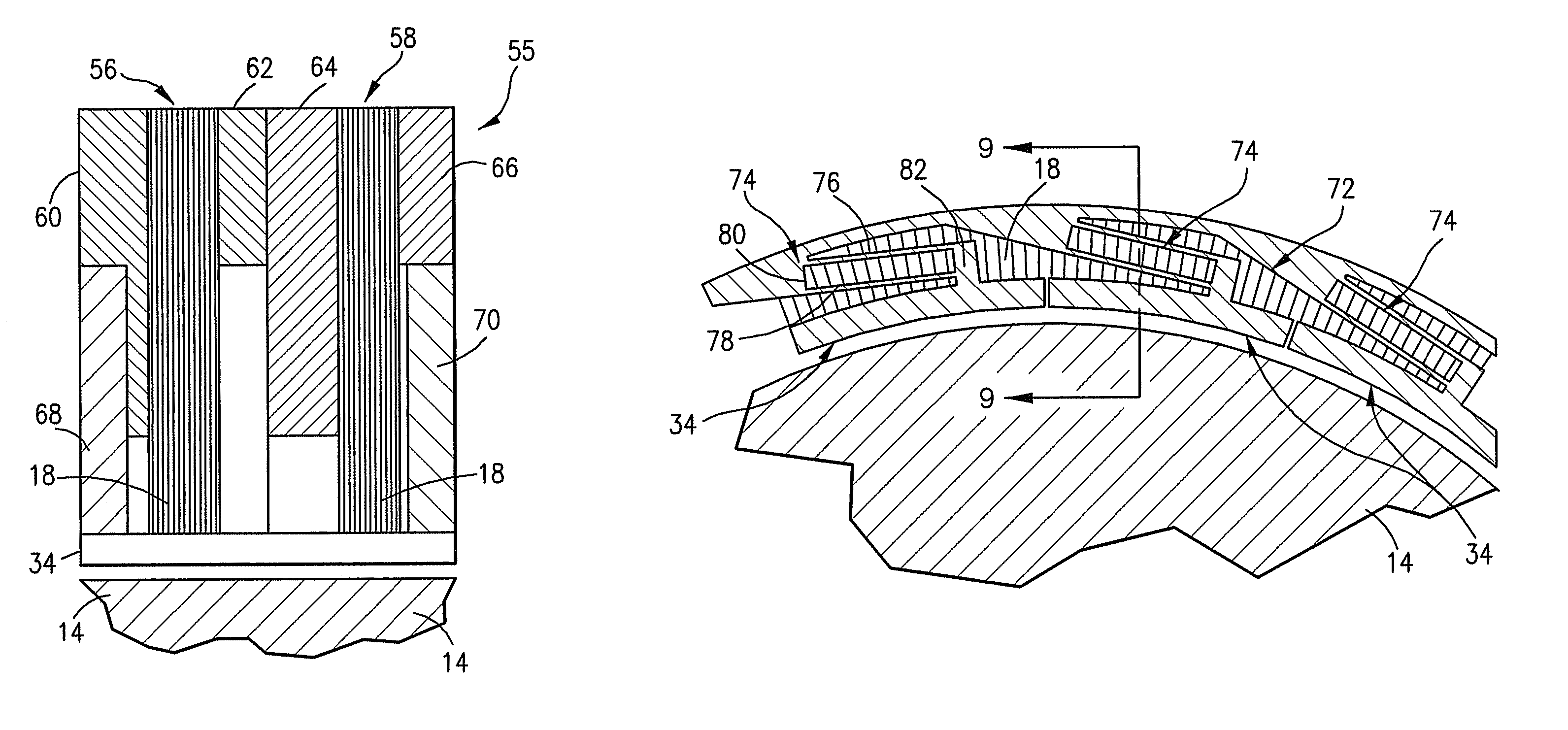
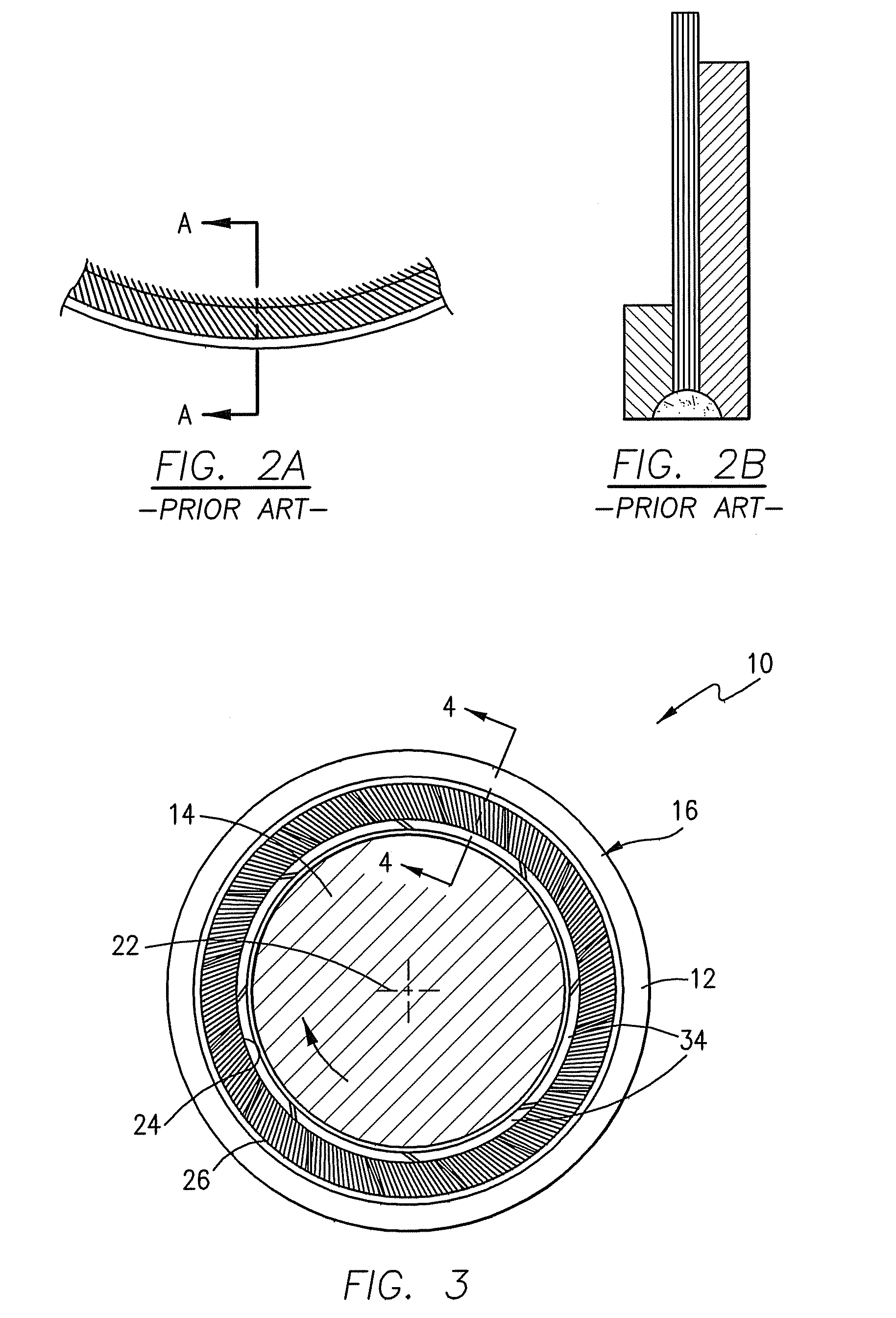
[0032]Referring initially to FIGS. 3-5, the hybrid bush seal 10 of this invention is intended to create a seal between two relatively rotating components, namely, a fixed stator 12 and a rotating rotor 14. In this embodiment, the seal 10 comprises a first group or bundle 16 of seal bristles 18 and a second bundle 20 of seal bristles 18 which are axially spaced from the first bundle 16. As used herein, the term “axial” or “axially spaced” refers to a direction along the longitudinal axis of the stator 12 and rotor 14, e.g. axis 22 in FIG. 3, whereas “radial” refers to a direction perpendicular to the longitudinal axis 22.

[0033]The seal bristles 18 in each bundle 16 and 20 have an inner end 24 and an outer end 26. In the embodiment illustrated in FIGS. 3 and 4, the outer end 26 of the seal bristles 18 in each bundle 16, 20 is affixed to the stator 12. For purposes of the present discussion, the construction and operation of the seal 10 herein is described with the seal bristles 18 in ...


PUM


Abstract

A hybrid brush seal is provided for sealing a circumferential gap between two machine components that are relatively rotatable with respect to each other having seal bristles mounted in a ring shape on a first machine component with bristle ends directed at the sealing surface of the second, rotating machine component. The bristle ends are kept from direct contact with the rotating machine component via one or more shoes which create a non-contact seal with the rotating machine component which is enhanced by the imposition of one or more spring elements connected between the machine component and shoes.

Description

RELATED APPLICATIONS[0001]This application is a continuation-in-part application of U.S. patent application Ser. No. 11 / 226,836 filed Sep. 14, 2005 now U.S. Pat. No. 7,182,345, which is a continuation of U.S. patent application Ser. No. 10 / 832,053 filed Apr. 26, 2004 now abandoned which claims the benefit of U.S. Provisional Application Ser. No. 60 / 466,979 filed May 1, 2003 under 35 U.S.C. § 119(e) for all commonly disclosed subject matter. U.S. Provisional Application Ser. No. 60 / 466,979 is expressly incorporated herein by reference in its entirety to form part of the present disclosure.FIELD OF THE INVENTION[0002]This invention relates to seals for sealing a circumferential gap between two machine components that are relatively rotatable with respect to each other, and, more particularly, to a hybrid brush seal having seal bristles mounted in a ring shape on a first machine component with bristle ends directed at the sealing surface of the second, rotating machine component. The b...

Claims


Application Information

Patent Timeline
Patent Type & Authority Patents(United States)
IPC IPC(8): F16D11/02F01D25/00F01D5/20
CPCF01D11/00F16J15/3288F01D11/02F05D2240/56
Inventor JUSTAK, JOHN F.
Owner SIEMENS ENERGY INC
Why Eureka
Try Eureka