Mounting bracket and snap-on cover assembly for use therewith

a technology of mounting brackets and snap-on covers, which is applied in the field of fencing systems, can solve the problems of confined spaces, material poses a bit of a problem, and it is difficult to connect horizontal vinyl rails to vertically extending posts

Inactive Publication Date: 2008-09-23
PLATT ROBERT E
View PDF30 Cites 25 Cited by
  • Summary
  • Abstract
  • Description
  • Claims
  • Application Information

AI Technical Summary

Benefits of technology

[0006]The mounting bracket assembly of the present invention comprises a bracket that is secured to a vertical fence post and a cover plate that is snap-fitted over the bracket after the rail has been retained within the bracket. The bracket is preferably substantially U-shaped and is mounted in such a way that it is open at a top end. The rail is dropped into the U-shaped bracket and fasteners are used to secure the rail within the bracket. The cover plate is snap fitted over the bracket after the rail has been retained therein so as to conceal the fasteners. The cover plate provides an aesthetically pleasing finish to the connection between the post and rail.

Problems solved by technology

While vinyl fencing is aesthetically pleasing and easy to maintain, the material poses somewhat of a problem for the contractor who must connect the various components together.
It is especially problematic to connect horizontal vinyl rails to vertically extending posts in confined spaces.

Method used


Image

  • Mounting bracket and snap-on cover assembly for use therewith
  • Mounting bracket and snap-on cover assembly for use therewith
  • Mounting bracket and snap-on cover assembly for use therewith

Examples


Embodiment Construction

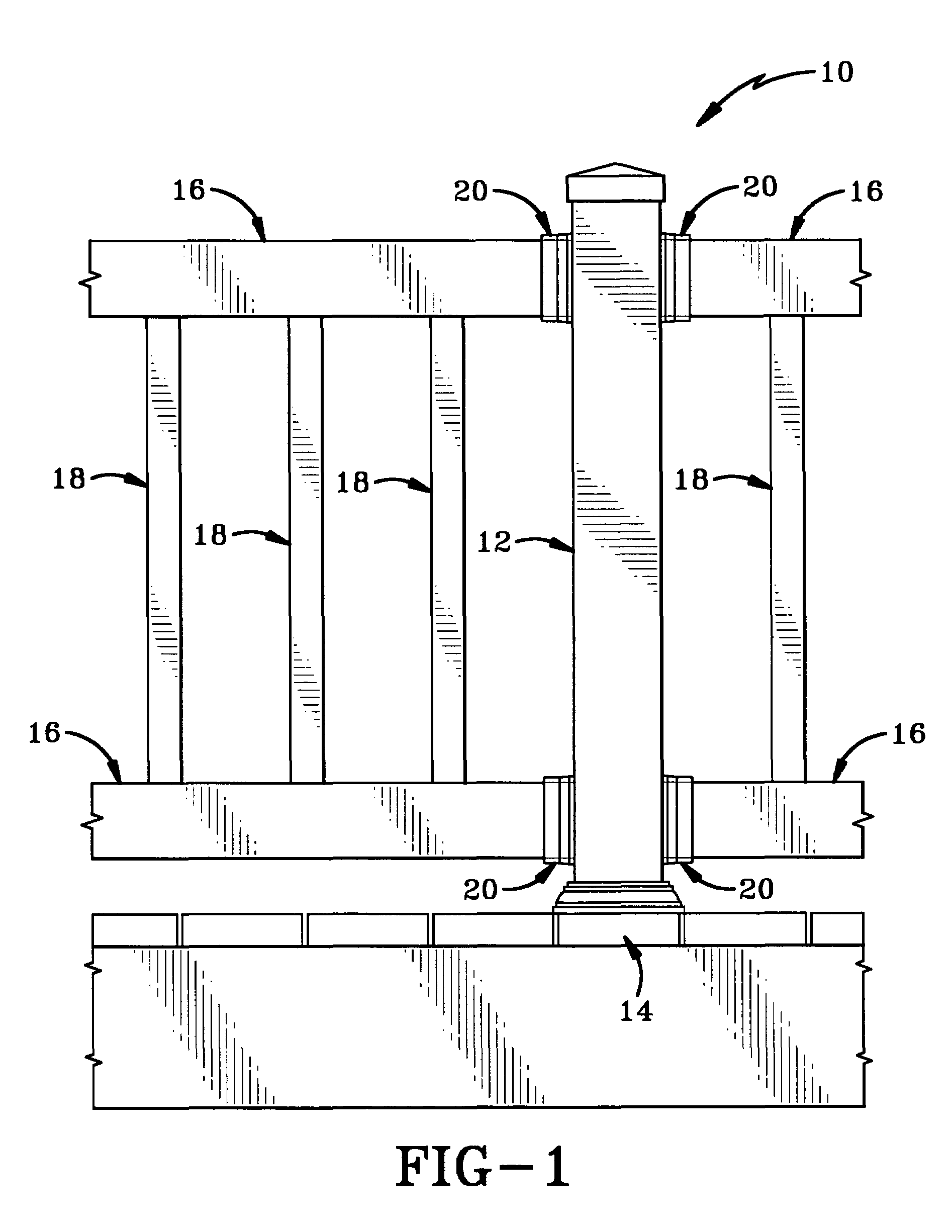
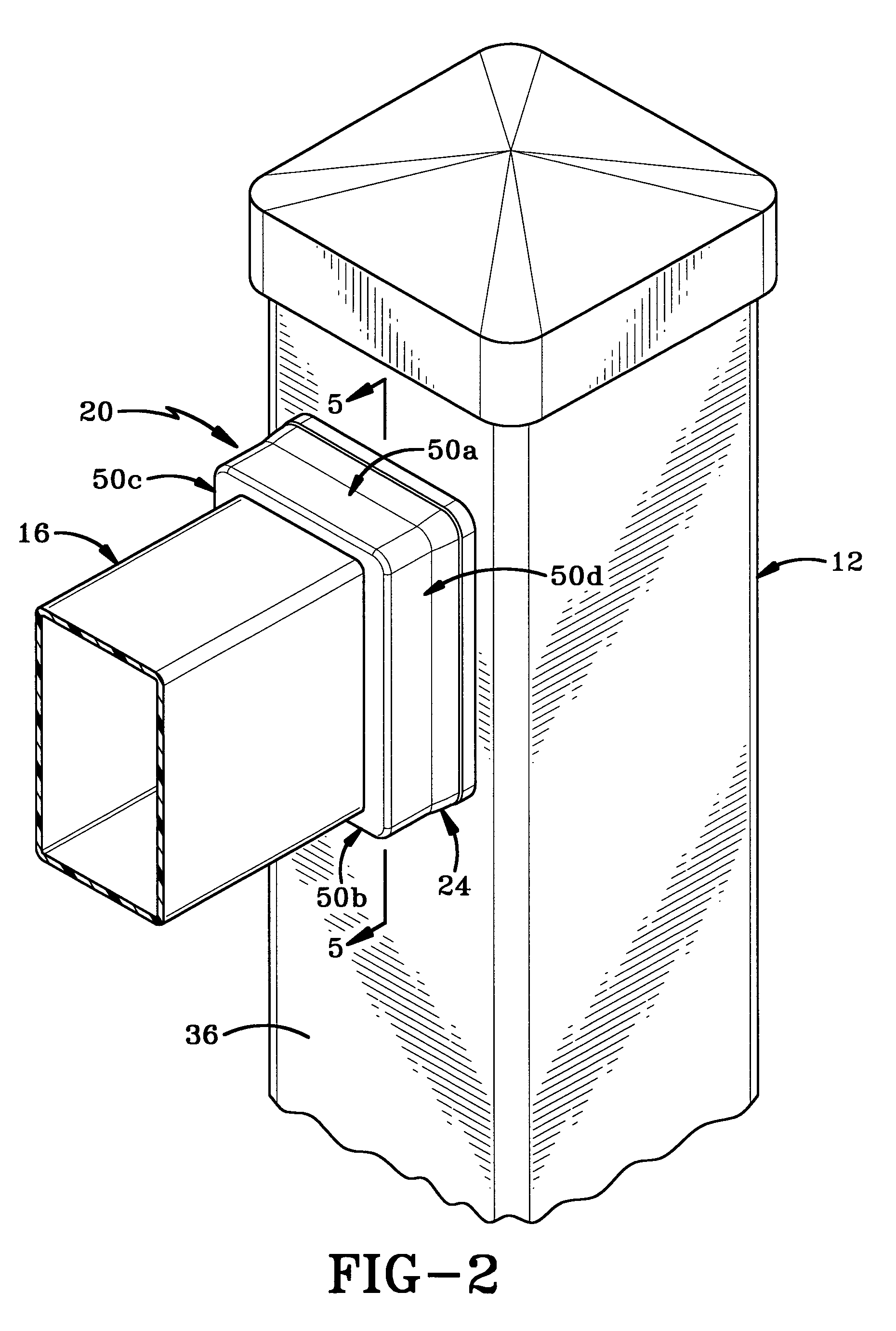
[0021]Referring to FIGS. 1&2, there is shown a section of a deck railing 10 including a post 12, mounted to deck planking 14, and having a plurality of rails 16 secured thereto. A plurality of balusters 18 extend between the upper and lower rails 16. Rails 16 are secured to post 12 by way of mounting bracket assemblies in accordance with the present invention and generally indicated at 20.

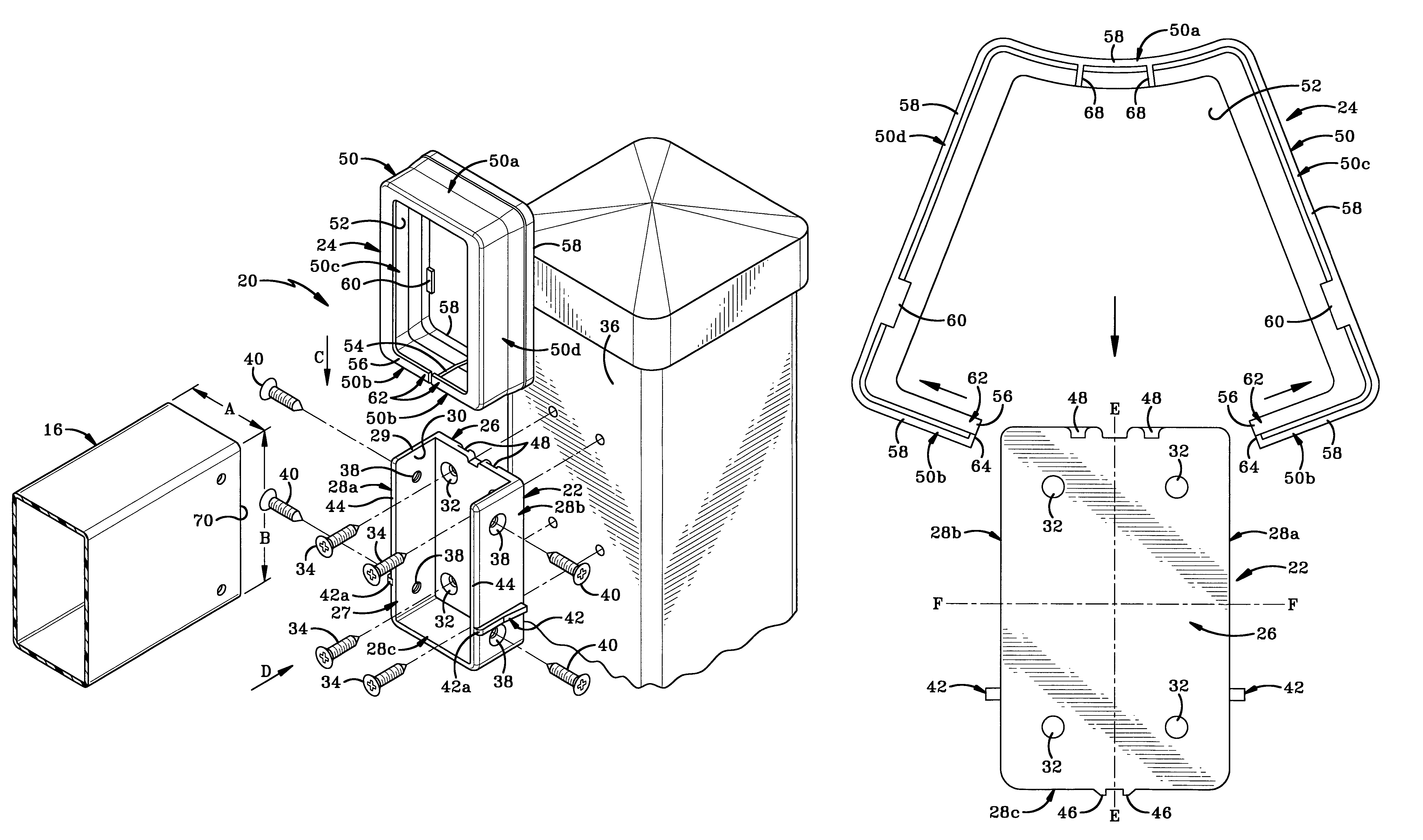
[0022]Referring to FIGS. 3-9, there is shown a rail 16 connected to a post 12 by way of the mounting bracket assembly 20 in accordance with the present invention. Bracket assembly 20 comprises a bracket 22 and a cover plate 24.

[0023]In accordance with a specific feature of the present invention, bracket 22 has a back wall 26, a peripheral outer wall 28 extending outwardly away from the back wall 26 and having an opening 30 formed therein. Opening 30 preferably extends entirely across one end of bracket 22. Peripheral outer wall 28 is substantially U-shaped with the opening 30 therein extending from...


PUM


Abstract

A bracket assembly for securing a rail to a post. The bracket assembly includes a bracket that is secured to the post and a spring-biased cover plate. The cover plate includes a perimeter wall that includes a slot which extends from its front edge through to its back edge. A portion of the perimeter wall terminates adjacent either side of the slot. These portions of the perimeter are movable relative to each other. The bracket includes a back wall with a peripheral outer wall extending upwardly and outwardly away therefrom. The peripheral wall defines a rail receiving receptacle into which an end of a rail is placed. The rail is preferably secured in position by a plurality of fasteners inserted through the rail and into the housing. Once the end of the rail is retained in the bracket, the terminal portions of the perimeter wall are arcuately separated from each other and the cover plate is snap-fitted over the peripheral outer wall of the bracket.

Description

BACKGROUND OF THE INVENTION[0001]1. Technical Field[0002]This invention generally relates to fencing systems. More particularly, the invention relates to mounting brackets useful for installing horizontal rails to vertical posts. Specifically, the invention relates to a bracket for mounting a rail to a post in confined spaces and to a cover plate that snaps around the bracket once the rail has been retained within the bracket.[0003]2. Background Information[0004]It has become more common in recent years to use either vinyl or plastic products for constructing fences for yards or deck railings. While vinyl fencing is aesthetically pleasing and easy to maintain, the material poses somewhat of a problem for the contractor who must connect the various components together. It is especially problematic to connect horizontal vinyl rails to vertically extending posts in confined spaces.[0005]There is therefore a need in the art for an improved bracket assembly for attaching horizontal rails...

Claims


Application Information

Patent Timeline
Patent Type & Authority Patents(United States)
IPC IPC(8): E04H17/14
CPCE04F11/181E04H17/1421E04H2017/1452E04F2011/1897E04H17/1452E04H17/1417E04H17/1488
Inventor PLATT, ROBERT E.
Owner PLATT ROBERT E
Why Eureka
Try Eureka