
Horizontally assembled steam generator
a horizontal assembly and steam generator technology, applied in the direction of steam generation using hot heat carriers, water circulation, lighting and heating apparatus, etc., can solve the problems of reduced steam generation efficiency, unsatisfactory efficiency loss, and comparative reduction in the effectiveness of the heating area concerned, and achieve low overall pressure loss and simplify the effect of distribution
- Summary
- Abstract
- Description
- Claims
- Application Information
AI Technical Summary
Benefits of technology
Problems solved by technology
Method used
Image

Examples
Embodiment Construction
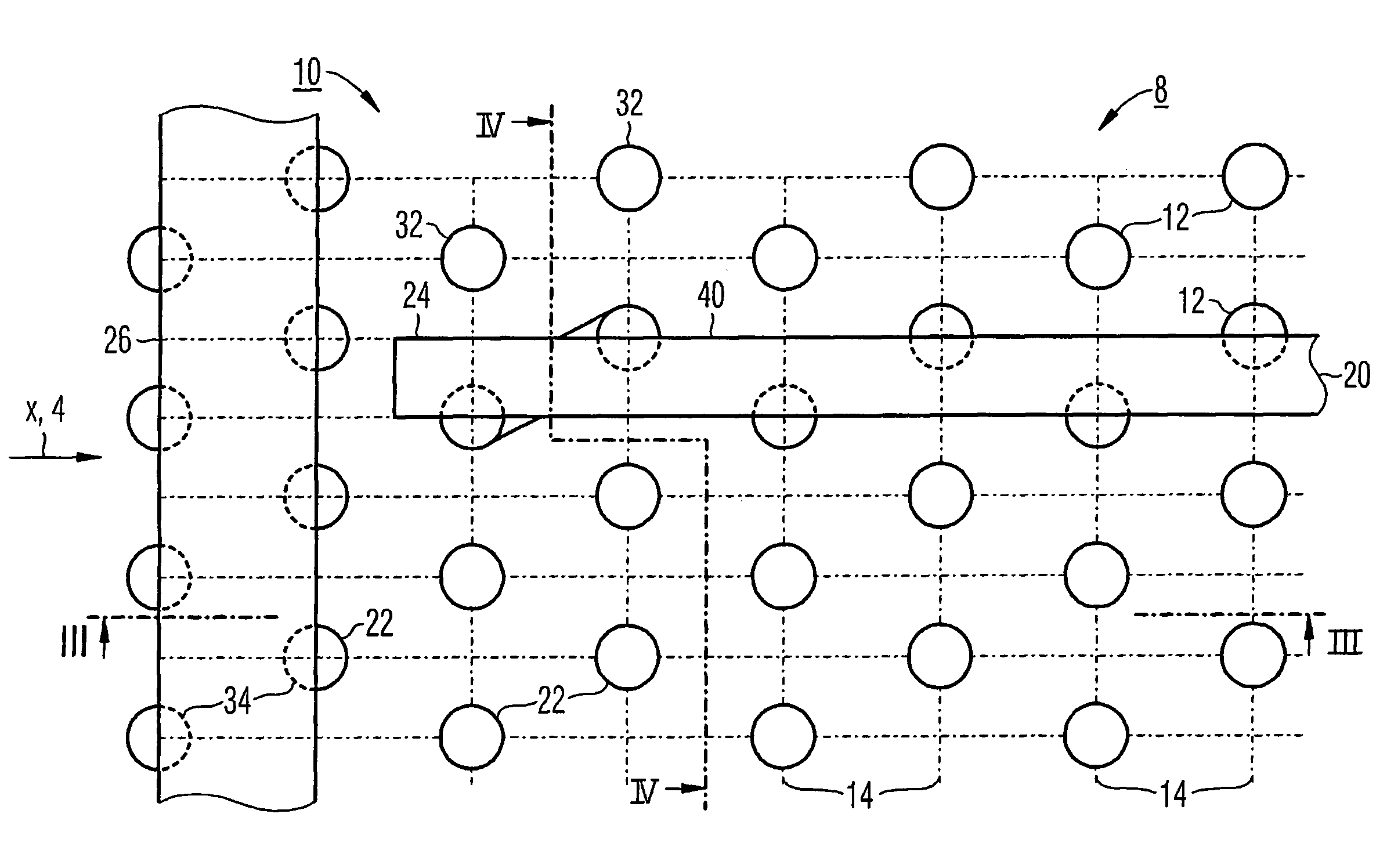
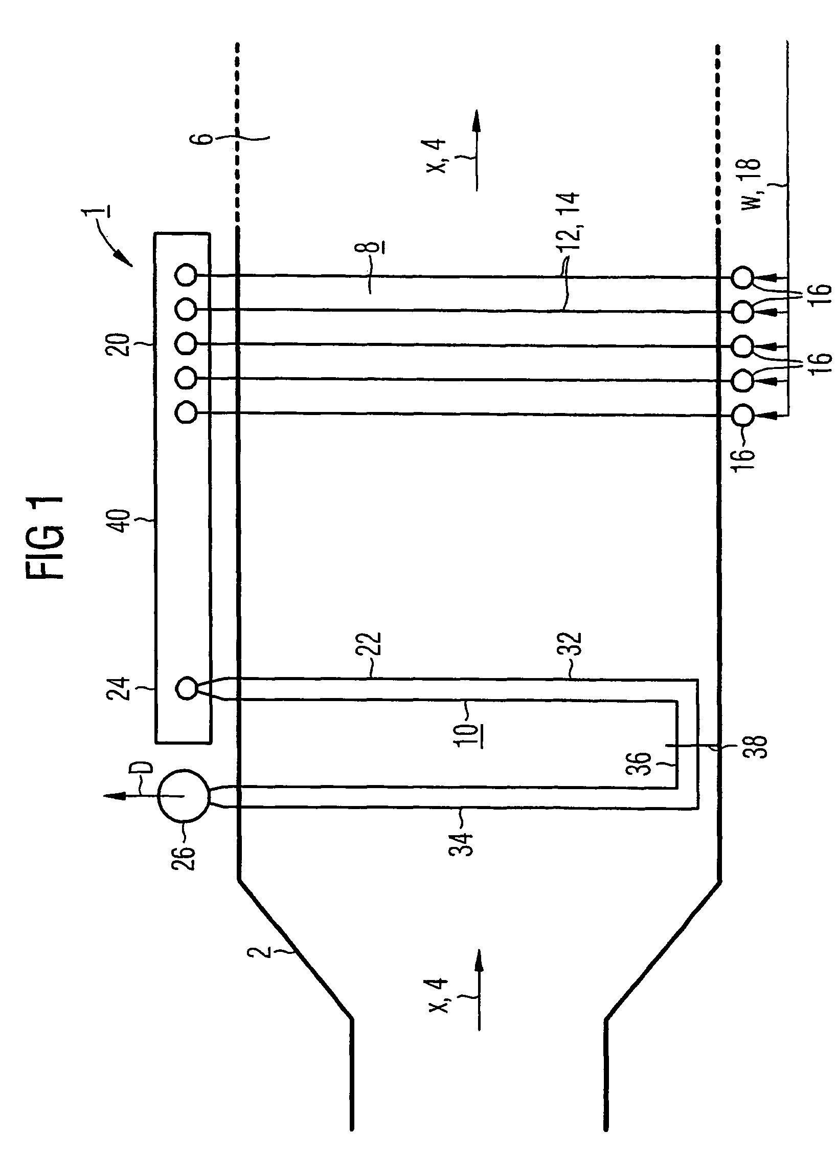
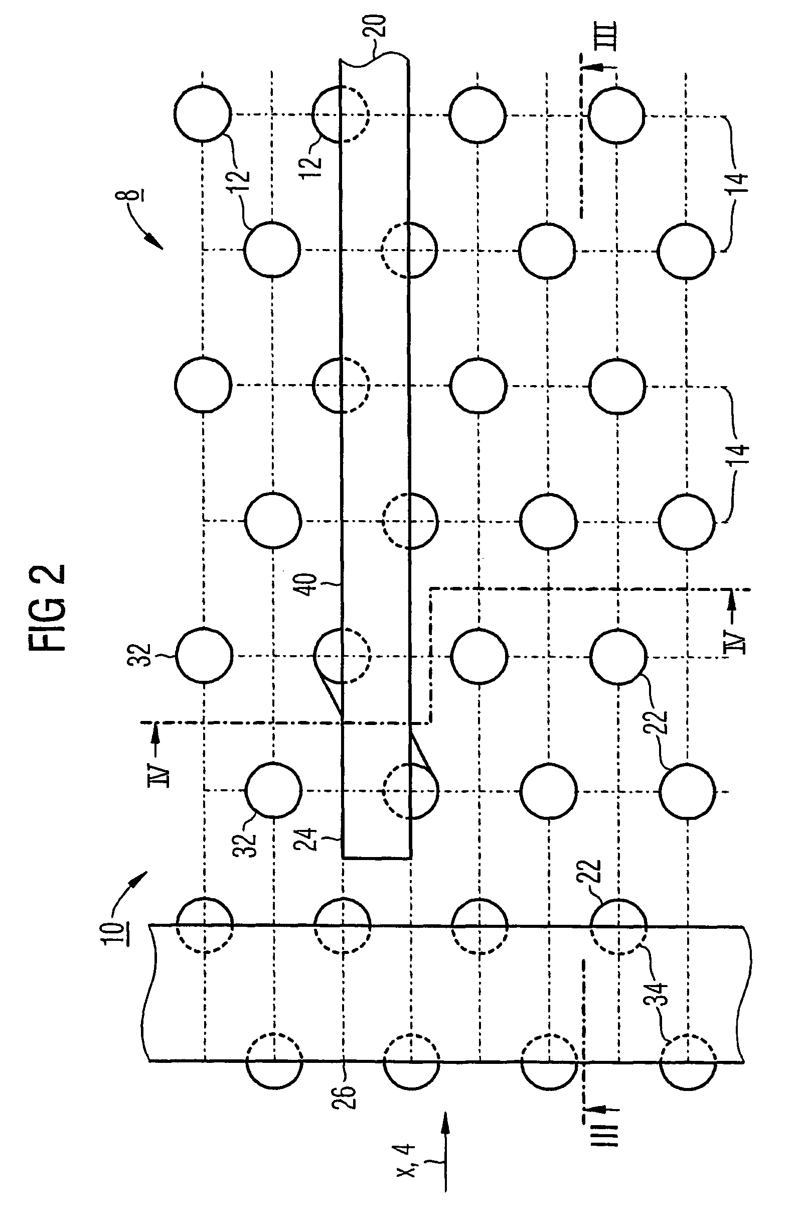
[0032]The steam generator 1 shown with its evaporator section in FIG. 1 is connected downstream in the manner of a waste-heat steam generator at the exhaust-gas end of a gas turbine, not shown in detail. The steam generator 1 has a containing wall 2 which forms a heating-gas duct 6 for the exhaust gas from the gas turbine, through which heating-gas duct said exhaust gas can flow in a approximately horizontal heating-gas-direction x indicated by the arrows 4. In the heating-gas duct 6 there are disposed a number (in the embodiment two) of evaporator heating areas 8, 10 which are configured in accordance with the once-through principle and which are connected behind one another for through flow by a flow medium W, D.
[0033]The multi-stage evaporator system formed from the evaporator / once-through heating areas 8, 10 can be loaded with a non-evaporated flow medium W which evaporates in a single pass through the evaporator / once-through heating areas 8, 10 and, after discharge from the eva...
PUM
 Abstract
Description
Claims
Application Information