Opposing parallel bladed retractor and method of use

a technology of parallel blades and retractors, applied in the field of retractors, can solve the problems of difficult manipulation of configuration, failure of retractors to include locking mechanisms, and inability to be readily interconnected with mechanical arms

Inactive Publication Date: 2008-11-25
RITLAND STEPHEN
View PDF362 Cites 74 Cited by
  • Summary
  • Abstract
  • Description
  • Claims
  • Application Information

AI Technical Summary

Problems solved by technology

For those instances where more than one blade is used, the retractors often have a configuration that is difficult to manipulate, and / or wherein the blades, when separated to displace tissue, are spread apart in an arcuate fashion, such that the blades are no longer parallel with the longitudinal axis of the retractor after the retractor is opened.
In addition, retractors fail to include a locking mechanism, and cannot be readily interconnected to a mechanical arm to hold the position of the retractor.
If during a spinal surgery a surgeon has a retractor in place and the pedicle screws have already been inserted into one or more vertebra during the surgery, and the surgeon then desires to subsequently tighten the pedicle screws, then if a bulky retractor is in place, the surgeon cannot readily access the screws.

Method used


Image

  • Opposing parallel bladed retractor and method of use
  • Opposing parallel bladed retractor and method of use
  • Opposing parallel bladed retractor and method of use

Examples


Embodiment Construction

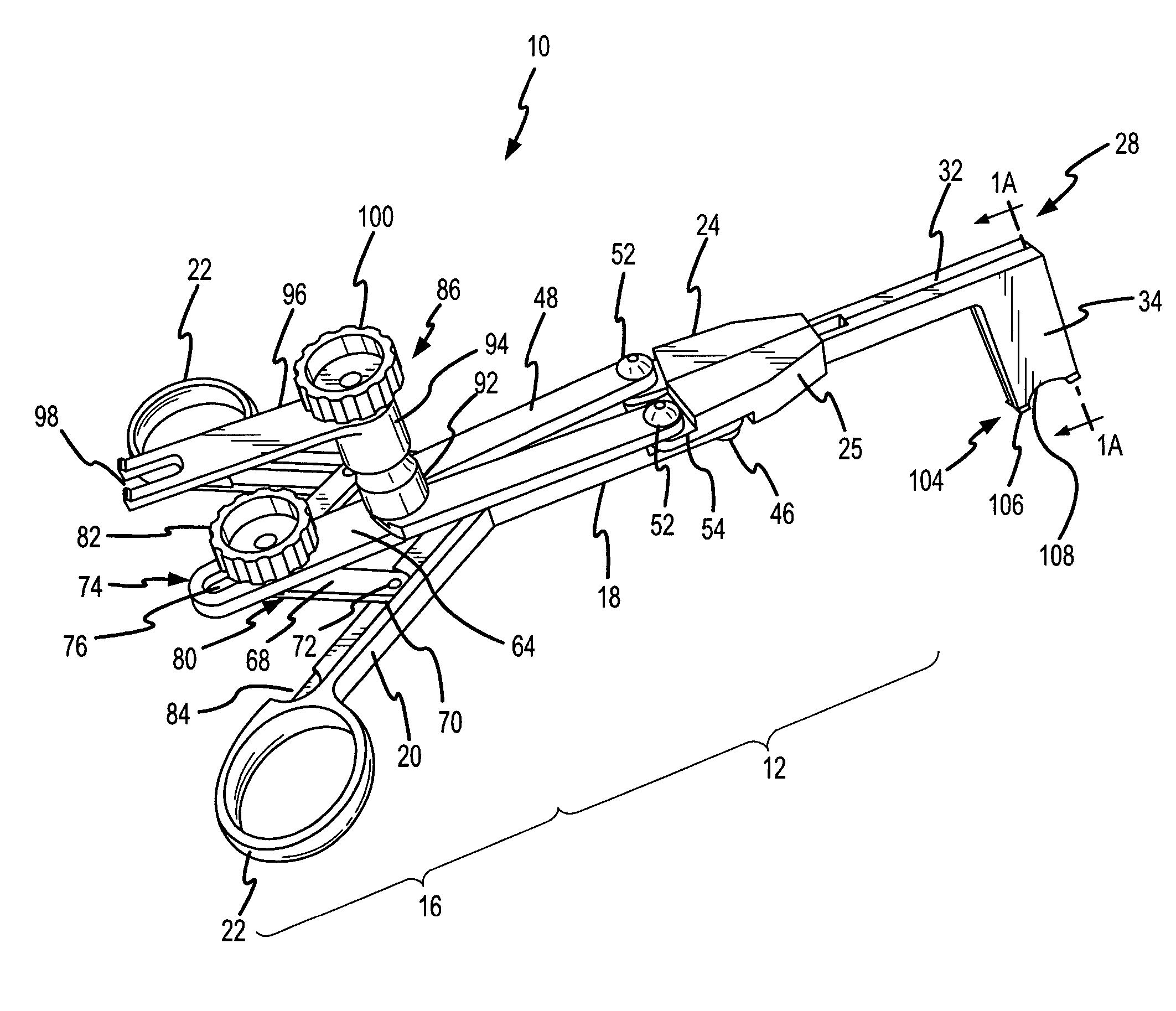
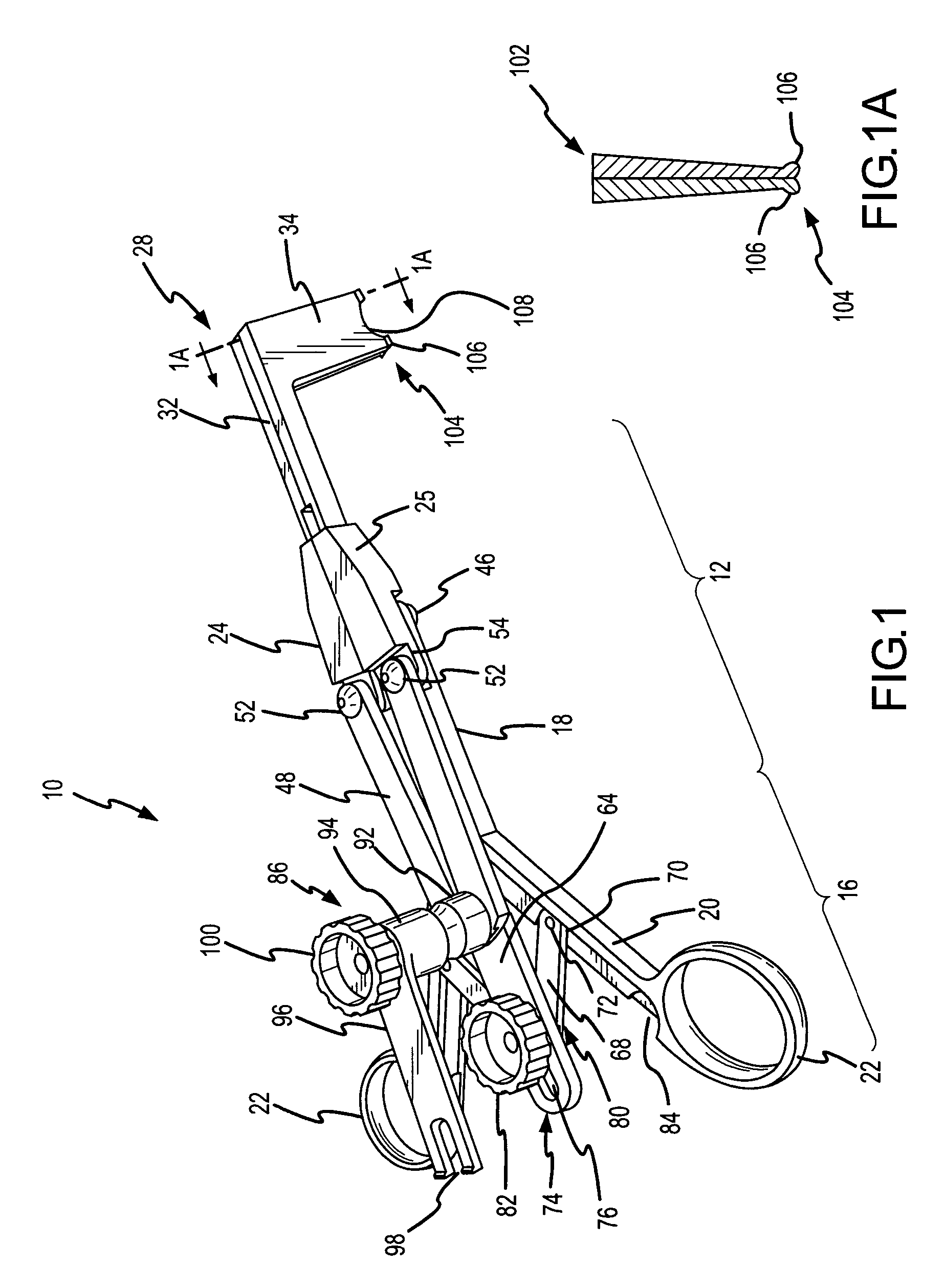
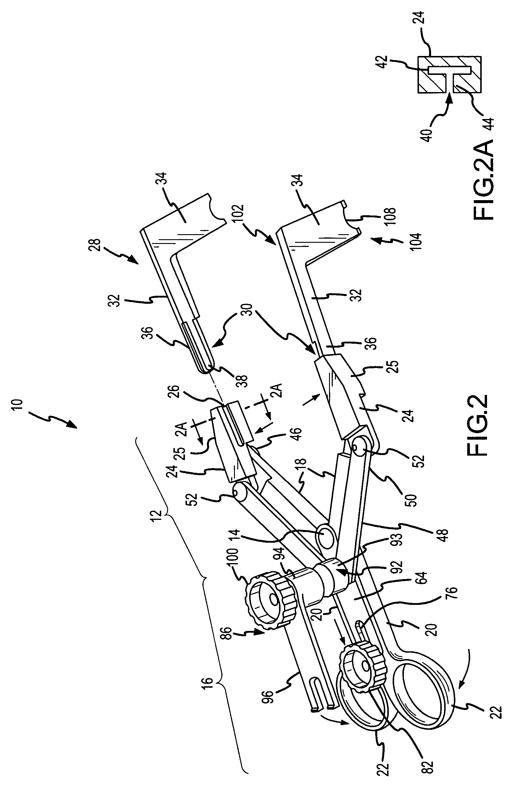
[0016]Referring now to FIGS. 1-3, a retractor apparatus constructed in accordance with an embodiment of the present invention is generally identified by reference numeral 10. Retractor 10 includes a front portion 12, a central hinge 14, and a rear or handle portion 16. The front portion 12 preferably includes opposing blade arms 18 that are interconnected to the blades as discussed below. The handle portion 16 preferably includes opposing handle arms 20. The handle arms 20 preferably include a contoured grip or handle opening 22 for a person, such as a surgeon, to grasp and manipulate the retractor 10.

[0017]Interconnected to the blade arms 18 of the front portion 12 are the blade receptacles 24. The blade receptacles 24 preferably include slots 26 for receiving blades 28. More particularly, one aspect of the present invention is to provide insertable and / or removable blades 28, wherein the blades 28 can be interchanged into the blade receptacles 24 with relative ease. The blade rece...


PUM


Abstract

A retractor is provided for maintaining substantially parallel blade alignment with the longitudinal axis of the retractor during opening and closing the retractor blades. The retractor includes rotatable blade receptacles and hinged blade arms interconnected to rotatable arms for maintaining the alignment of the blades during opening and closing. In addition, the retractor may include interchangeable blades, means for locking the blade position, and means for securing the retractor to a mechanical arm.

Description

CROSS-REFERENCE TO RELATED APPLICATIONS[0001]Priority is claimed from U.S. Provisional Patent Application No. 60 / 611,836 filed Sep. 20, 2004 entitled “Opposing Parallel Bladed Retractor and Method of Use,” which is incorporated herein by reference in its entirety.FIELD OF THE INVENTION[0002]The present invention is directed to retractor for use in surgical procedures, and methods of use for the retractor.BACKGROUND OF THE INVENTION[0003]Many existing retractors for surgical procedures utilize a single blade. For those instances where more than one blade is used, the retractors often have a configuration that is difficult to manipulate, and / or wherein the blades, when separated to displace tissue, are spread apart in an arcuate fashion, such that the blades are no longer parallel with the longitudinal axis of the retractor after the retractor is opened. In addition, retractors fail to include a locking mechanism, and cannot be readily interconnected to a mechanical arm to hold the po...

Claims


Application Information

Patent Timeline
Patent Type & Authority Patents(United States)
IPC IPC(8): A61B1/32
CPCA61B17/02A61B17/2812A61B17/2833A61B2017/00473
Inventor RITLAND, STEPHEN
Owner RITLAND STEPHEN
Why Eureka
Try Eureka