Wind power generator

a wind power generator and wind power technology, applied in the direction of electric generator control, motor/generator/converter stopper, dynamo-electric converter control, etc., can solve the problems of reducing power generation efficiency, unable to rotate by weak winds, and large equipment structure, etc., to achieve the effect of suppressing noise and vibration

Inactive Publication Date: 2008-11-25
ZEPHYR
View PDF36 Cites 101 Cited by
  • Summary
  • Abstract
  • Description
  • Claims
  • Application Information

AI Technical Summary

Benefits of technology

[0012]The first object of the present invention is to provide a wind power generating device capable of suppressing noise and vibration at the time of strong wind.
[0013]The second object of the present invention is to provide a wind power generating device capable of maintained power generation while reducing the number of rotations even at the time of strong wind.
[0014]The third object of the present invention is to provide a wind power generating device capable of maintained power generation while reducing the number of rotations even at the time of strong wind and also capable of suppressing the change in discharge / charge current of a storage battery to a minimum level.
[0015]The fourth object of the present invention is provide a wind power generating device with a start-assisting function capable of rotating even at the time of weak wind and also capable of saving power consumption as much as possible at the time of rotation start-assisting with the start-assisting function corresponding to a small sized wind power generating device [adg1].

Problems solved by technology

However, when generating large amounts of power, equipment becomes structurally large and accordingly uneconomical.
Accordingly, the power generating efficiency degrades, which is a problem.
Therefore, it cannot be rotated by weak winds and sufficient power generating efficiency cannot be obtained, which is a problem.

Method used


Image

  • Wind power generator
  • Wind power generator
  • Wind power generator

Examples


Embodiment Construction

[0030]The preferred embodiments of the present invention are described below with reference to the drawings.

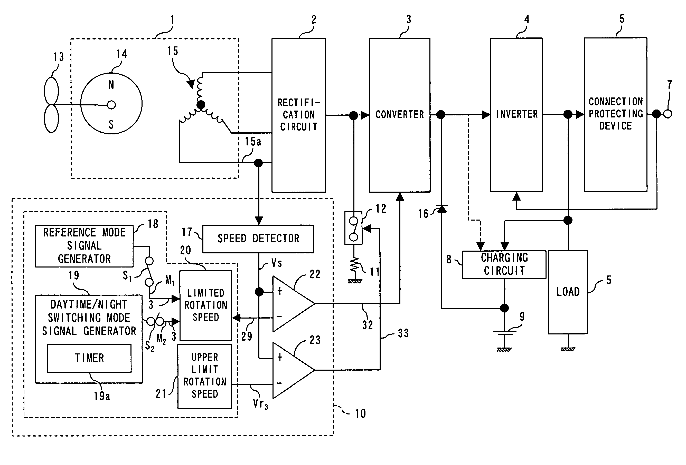
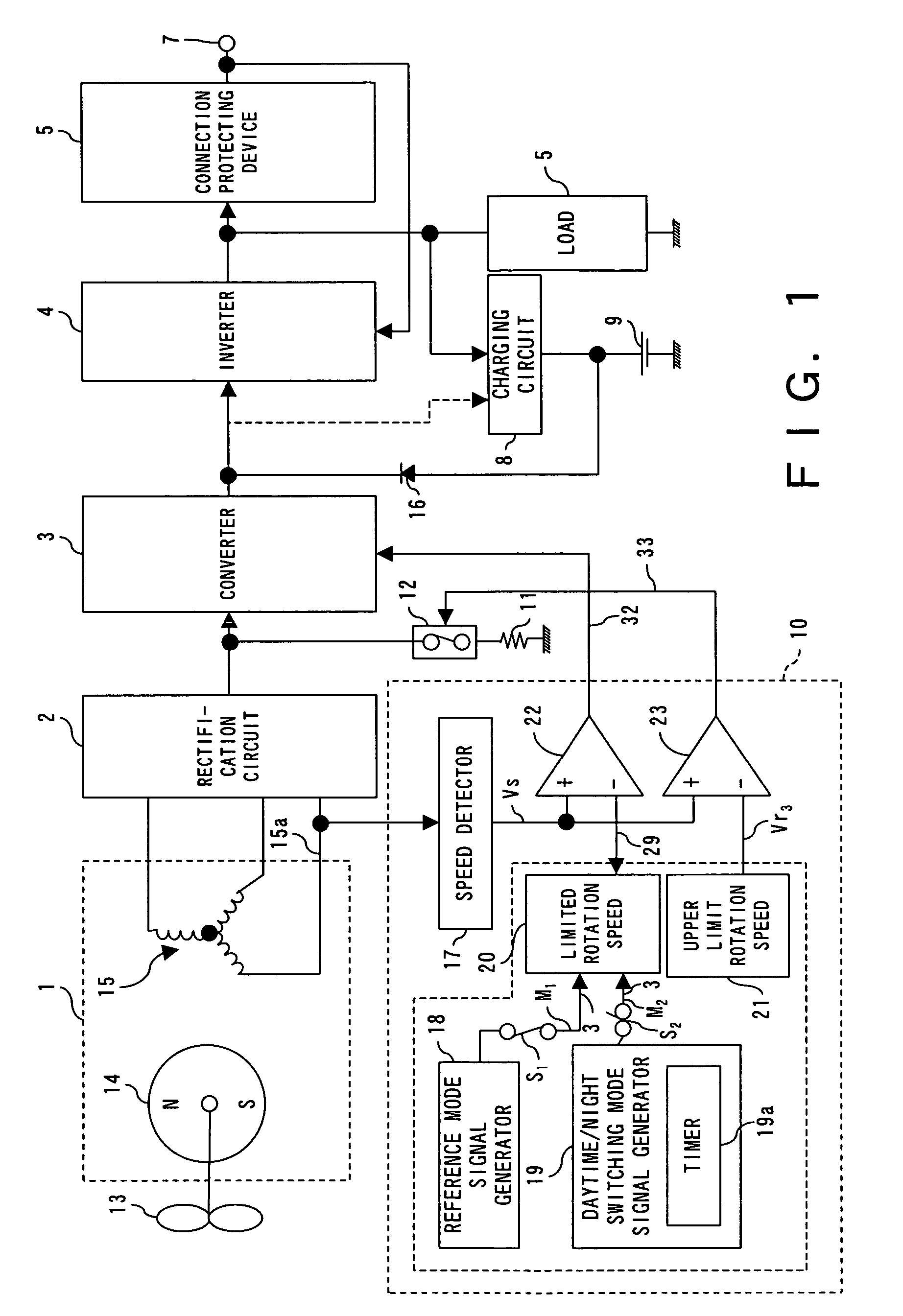
[0031]FIG. 1 shows the configuration of a wind power generator power control device in the first preferred embodiment of the present invention.

[0032]The wind power generator power control device comprises a wind power generator 1, a rectification circuit 2, a DC / DC converter 3 as an output current control means and a DC / DC conversion means, an inverter 4, a load 5, a connection protecting device 6, AC mains connecting terminal 7, a charging circuit 8, a storage battery 9, a rotation control circuit 10, an upper limited rotation speed setting fixed load 11 and a switch 12.

[0033]The wind power generator 1 is a publicly known AC generator comprising a rotor 13 constructed from a permanent magnet connected to a windmill 13 and a stator with a three-phase armature coil 15. This AC generator can be an external magnet type or a built-in magnet type.

[0034]The rectification circuit 2 a...


PUM


Abstract

When a wind velocity sensor detects a wind velocity higher than a predetermined level, a timer device starts a waiting timer function during an operation timer period shorter than the waiting timer period. After the waiting timer period is over, the waiting timer function is switched to an operation timer function, and a switching relay switches a generator to a motor only during an operation timer period. Then, a driving circuit performs a start assisting rotation. After the operation timer period is over, the waiting timer period re-starts. This process is repeated. When during this period, the number of rotations of a rotor monitored by a rotation number measuring device, based on the output voltage Vm of a three-phase conduction coil exceeds a predetermined number of rotations, the charging of a battery by a three-phase generator is started.

Description

TECHNICAL FIELD[0001]The present invention relates to a wind power generating device.BACKGROUND ART[0002]Conventionally, there are a variety of types of wind power generators, and each type of wind power generator has different characteristics. For example, when classifying wind power generators by the direction of attachment of a shaft for supporting a windmill, they are divided into a vertical shaft type the direction of attachment of the shaft of which is vertical and a horizontal shaft type the direction of attachment of the shaft of which is horizontal. The vertical type includes the Savonius windmill, the Darius windmill and the like, and the horizontal type includes the propeller type and the like.[0003]When classifying them with regard to whether they function predominantly based on a torque for rotating a windmill, generated by drag or lift, they are divided into a drag type in which drag mainly functions, a lift type in which lift mainly functions and a drag / lift type in w...

Claims


Application Information

Patent Timeline
Patent Type & Authority Patents(United States)
IPC IPC(8): F03D9/00H02P9/04H02P15/00H02P9/06H02P3/00H02P9/00H02P9/08
CPCH02P9/08F03D7/026F03D7/0272Y02E10/721Y02E10/723Y02E10/725F05B2220/7068Y02E10/72
Inventor ITO, RYOSUKESATO, KIYOSHITAMURA, HIDEAKIKAWAKAMI, KATSUSHI
Owner ZEPHYR
Why Eureka
Try Eureka