Rotary impact tool

a rotary and tool technology, applied in the field of rotary impact tools, can solve problems such as unpleasant noise and vibration, and achieve the effect of suppressing noise and vibration

Inactive Publication Date: 2015-06-11
PANASONIC INTELLECTUAL PROPERTY MANAGEMENT CO LTD
View PDF9 Cites 6 Cited by
  • Summary
  • Abstract
  • Description
  • Claims
  • Application Information

AI Technical Summary

Benefits of technology

[0007]Accordingly, it is an object of the present invention to provide a rotary impact tool configured to suppress noise and vibration from being generated at an impact.

Problems solved by technology

When the hammers rotate, the needle roller is brought into contact with the grooves in the rotating direction of the hammers to generate unpleasant noise and vibration.

Method used


Image

  • Rotary impact tool
  • Rotary impact tool
  • Rotary impact tool

Examples


Embodiment Construction

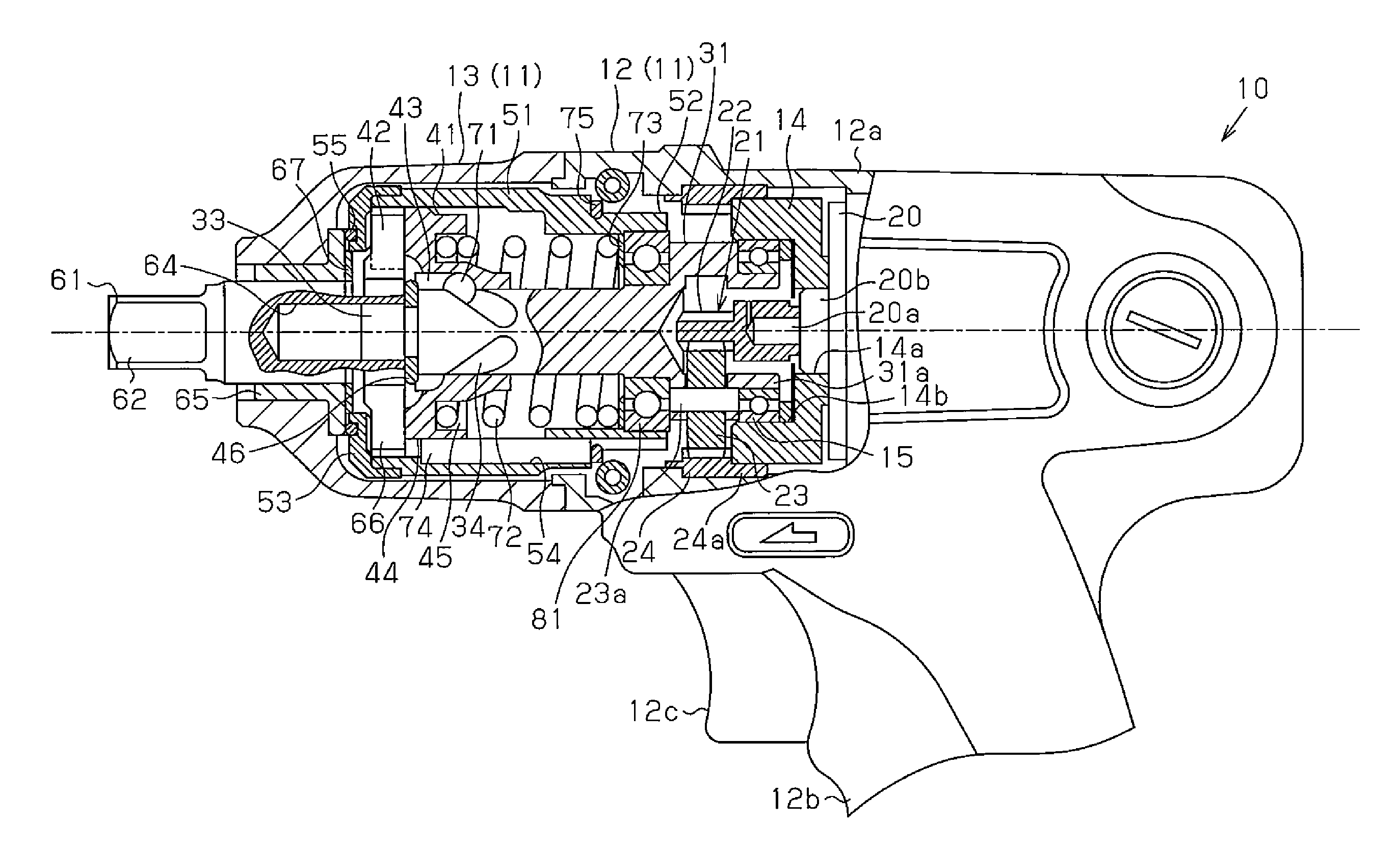
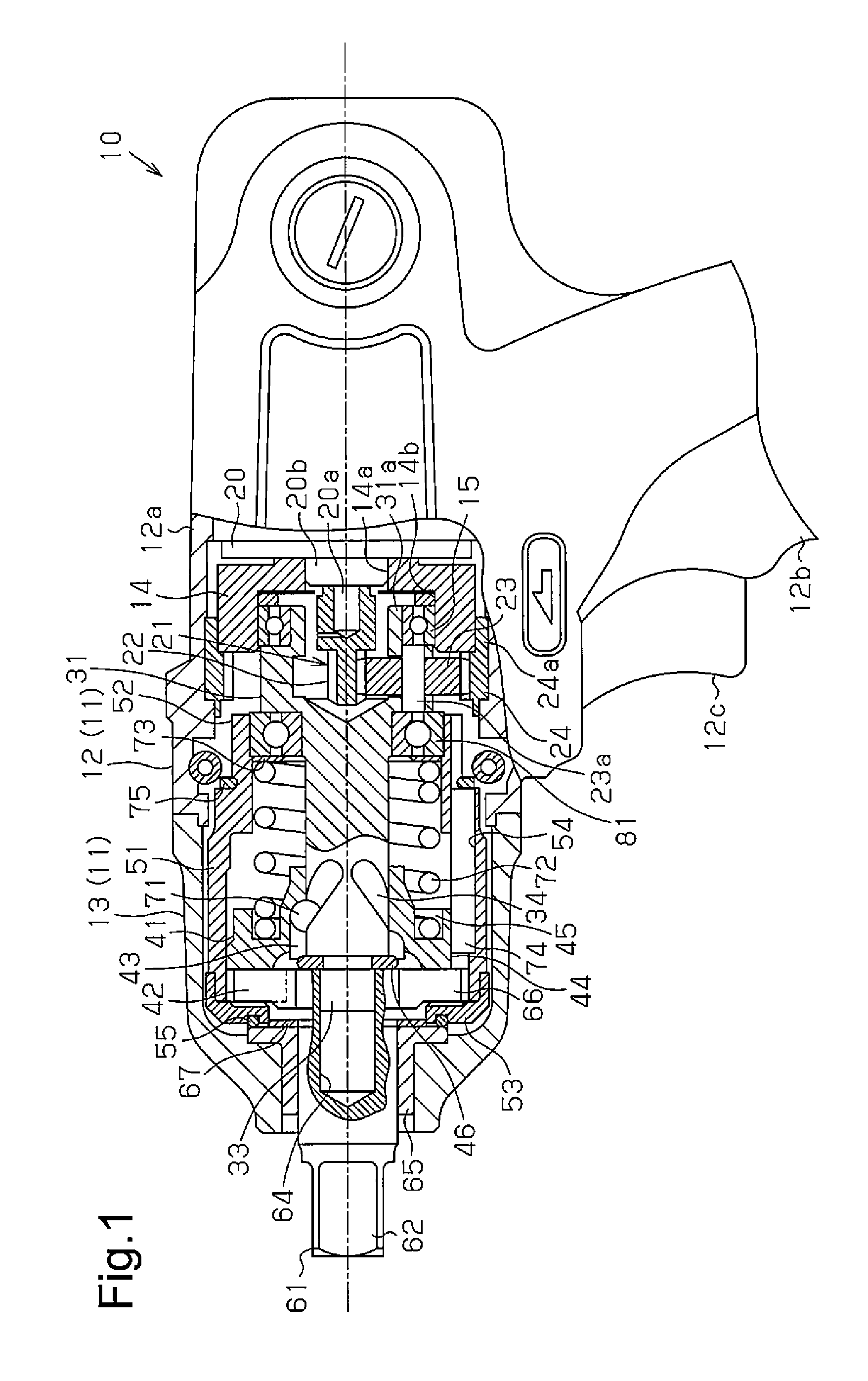
[0016]An embodiment of a rotary impact tool will be described below with reference to the accompanying drawings. As shown in FIG. 1, a rotary impact tool 10 is used as, for example, an impact wrench, and includes various members such as a drive unit 20 and a power transmitting mechanism 21 that are stored in a housing 11.

[0017]The housing 11 is configured of a rear housing 12 made of a synthetic resin and arranged at the rear end of the rotary impact tool 10 and a front housing 13 made of aluminum and arranged at the front end of the rotary impact tool 10.

[0018]The rear housing 12 has a cylindrical storing unit 12a in which the drive unit 20 configured of a motor and the power transmitting mechanism 21 for transmitting a rotational drive force of the drive unit 20 are stored and a grip portion 12b extending downward from the storing unit 12a to form a substantially T shape. On the grip portion 12b, an operation 12c switch 12c that can be press-controlled with a user is formed. At th...


PUM


Abstract

A rotary impact tool includes an engagement element inserted into a hole formed by first and second grooves between a main hammer and a sub-hummer. The engagement element engages the main hammer with the sub-hammer in a rotating direction. The engagement element includes a core material and an elastic member covering an outer periphery of the core material.

Description

CROSS-REFERENCE TO RELATED APPLICATIONS[0001]This application is based upon and claims the benefit of priority from prior Japanese Patent Application No. 2013-256207, filed on Dec. 11, 2013, the entire contents of which are incorporated herein by reference.BACKGROUND OF THE INVENTION[0002]The present invention relates to a rotary impact tool.[0003]A conventional rotary impact tool in which a main hammer and a sub-hammer strike an anvil in a rotating direction to fasten a bolt or a nut is known (for example, see Japanese Patent No. 4457170).[0004]The rotary impact tool of Japanese Patent No. 4457170 suppresses so-called misalignment rotation in which an axial line of rotation of the sub-hammer from a central axial line of rotation of a spindle. In this manner, a rotational striking force obtained by a hammer is suppressed from being reduced while vibration in an axial line direction is moderated.[0005]In the rotary impact tool as described above, grooves are formed in the main hammer...

Claims


Application Information

Patent Timeline
Patent Type & Authority Applications(United States)
IPC IPC(8): B25B21/02B25D17/11
CPCB25D17/11B25B21/02B25B21/026
Inventor TSUBAKIMOTO, HIROYUKI
Owner PANASONIC INTELLECTUAL PROPERTY MANAGEMENT CO LTD
Why Eureka
Try Eureka