Aircraft propelled by a turbojet engine with contrarotating fans

a technology of contrarotating fans and turbojet engines, which is applied in the field of aircraft, can solve the problems of low propulsion efficiency, low fuel consumption of aircraft, and low ejection speed of gas stream passing through the engine, and achieve the effect of limiting aerodynamic drag, sound nuisance and fuel consumption of aircra

Active Publication Date: 2015-10-15
SN DETUDE & DE CONSTR DE MOTEURS DAVIATION S N E C M A
View PDF48 Cites 79 Cited by
  • Summary
  • Abstract
  • Description
  • Claims
  • Application Information

AI Technical Summary

Benefits of technology

[0006]An object of the present invention is to propose another aircraft architecture that enables sound nuisance and fuel consumption of the aircraft to be reduced by limiting aerodynamic drag by taking in the boundary layer.
[0008]The turbojet of the aircraft in accordance with the invention is incorporated in the rear of the fuselage, in line therewith, and without having recourse to a pylon. As a result, the aerodynamic drag induced by the turbojet is reduced. Furthermore, the turbojet ingests a portion of the boundary layer that is formed around the fuselage of the aircraft via air intakes, with the remaining portion of the boundary layer then being ingested by the fans. Since the speed of the boundary layer is low, the admission speed and thus the ejection speed of the gas stream passing through the engine is also low. This results in high propulsion efficiency and low levels of sound nuisance.
[0010]Preferably, the fans present an outside diameter that is substantially identical to the maximum diameter of the fuselage of the aircraft, thereby making it possible to obtain a high bypass ratio for better propulsion efficiency. In addition, the fuselage of the aircraft tends to mask the air intake to the fans, thereby protecting them from ingesting foreign bodies and limiting the noise radiated by the fans.

Problems solved by technology

Since the speed of the boundary layer is low, the admission speed and thus the ejection speed of the gas stream passing through the engine is also low.
This results in high propulsion efficiency and low levels of sound nuisance.

Method used


Image

  • Aircraft propelled by a turbojet engine with contrarotating fans
  • Aircraft propelled by a turbojet engine with contrarotating fans

Examples


Embodiment Construction

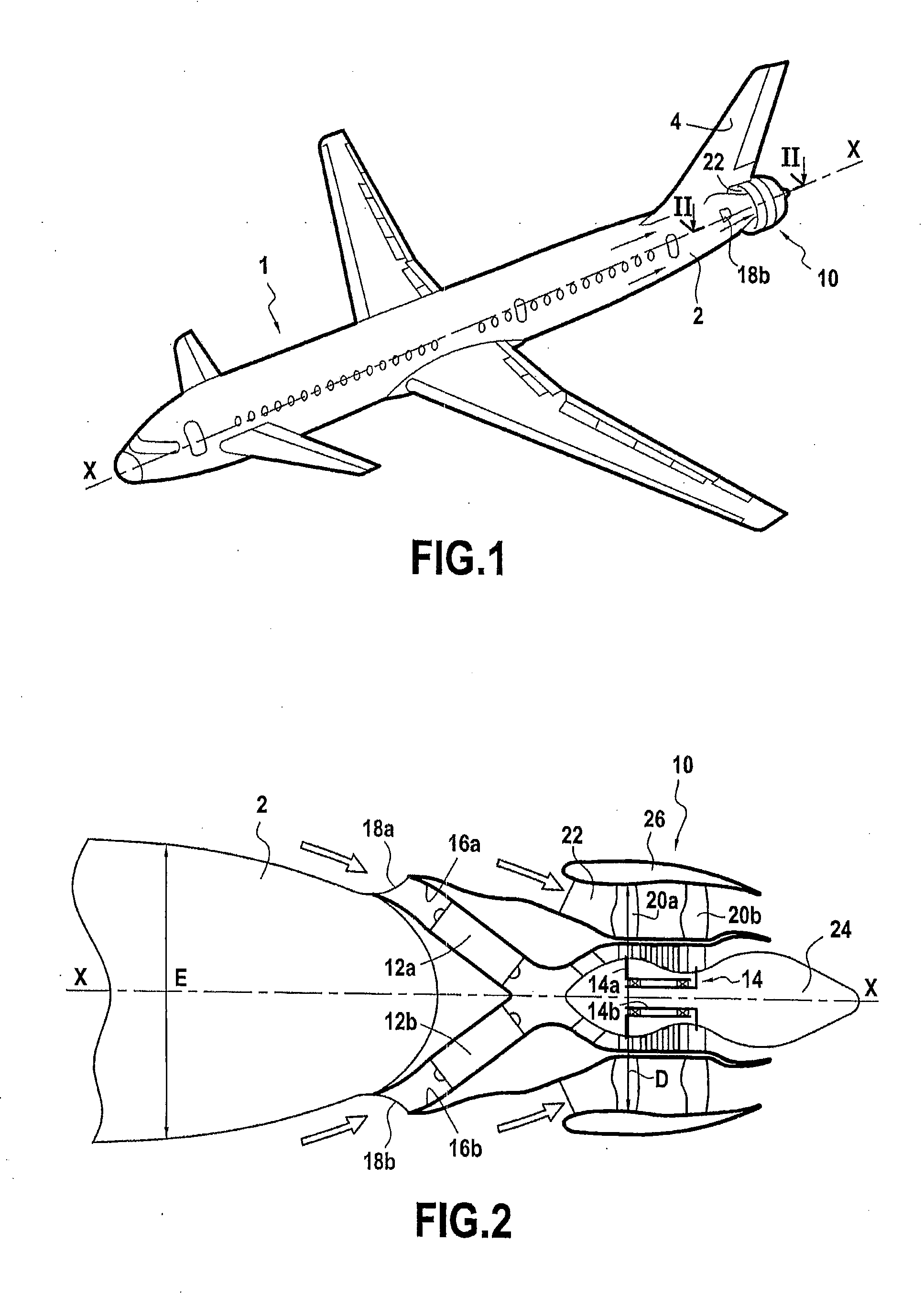
[0017]The invention relates to any aircraft, whether civil or military, e.g. to drones and to civil airplanes of the kind shown in FIG. 1.

[0018]FIG. 1 thus shows a civil airplane 1 in accordance with the invention. The airplane has a turbojet 10 incorporated at the rear of the fuselage 2 of the airplane, in line therewith.

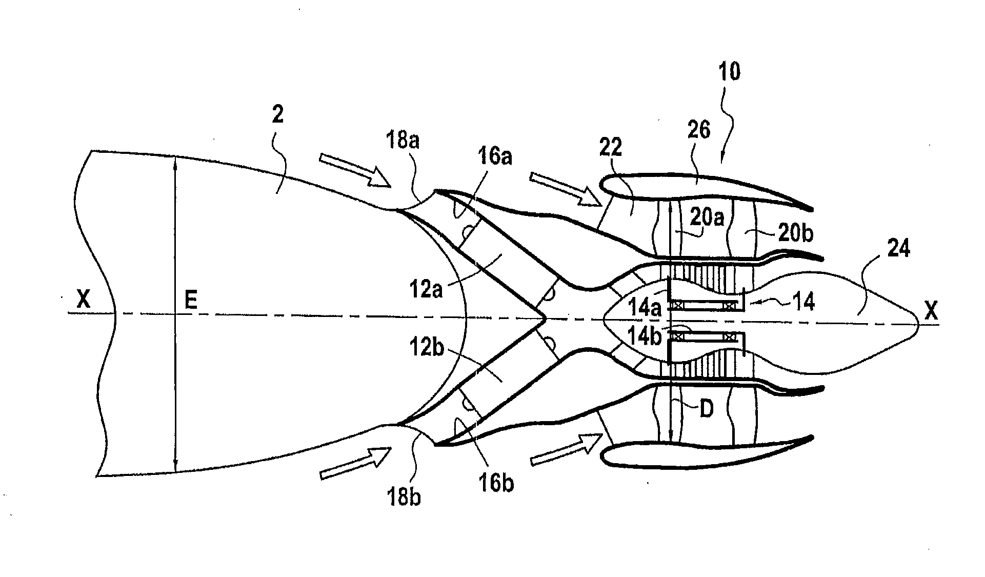
[0019]As shown more clearly in FIG. 2, the turbojet 10 is centered on a longitudinal axis X-X of the fuselage 2 of the airplane. The turbojet comprises in particular, from upstream to downstream in the gas flow direction, two distinct gas generators 12a and 12b that are arranged in parallel and that feed a single working turbine 14.

[0020]In known manner, each gas generator 12a, 12b comprises a low pressure compressor, a high pressure compressor, a combustion chamber, a low pressure turbine, and a high pressure turbine (not shown in the figures).

[0021]Furthermore, each gas generator 12a, 12b is housed in a respective primary flow passage 16a, 16b. Between them, thes...


PUM


Abstract

An aircraft propelled by a turbojet having contrarotating fans, the turbojet being incorporated at the rear of a fuselage of the aircraft and in line therewith and including two gas generators that feed a working turbine having two contrarotating turbine rotors for driving two fans arranged downstream from the gas generators, and distinct air intakes for feeding each gas generator, the air intakes being connected to the fuselage of the aircraft so as to take in at least a portion of the boundary layer formed around the fuselage of the aircraft.

Description

BACKGROUND OF THE INVENTION[0001]The present invention relates to the general field of aircraft, and in particular to civil airplanes, which aircraft are propelled by a bypass turbojet incorporated in part in the fuselage of the aircraft.[0002]Civil airplanes are generally fitted with turbojets mounted under the wings or in a rear position on the fuselage, and they are fastened thereto by means of pylons.[0003]Because of the increase in the cost of fuel expected in the years to come, engine manufacturers are seeking to reduce the fuel consumption of civil airplanes. One of the ways envisaged for doing this is to embed the engines at least in part inside the fuselage of an airplane in order to eliminate the pylons and the fairings of the engines, thereby reducing the weight of the propulsion unit and reducing its drag. The sound nuisance from the airplane is also reduced thereby.[0004]Furthermore, in flight, a boundary layer forms around the fuselage of the airplane and generates aer...

Claims


Application Information

Patent Timeline
Patent Type & Authority Applications(United States)
IPC IPC(8): B64D27/20B64D33/02F01D13/02B64D27/14
CPCB64D27/20F01D13/02B64D33/02B64D27/14B64D2027/005B64D2033/0273B64D2033/0286F02C6/02Y02T50/40Y02T50/60
Inventor GALLET, FRANCOIS
Owner SN DETUDE & DE CONSTR DE MOTEURS DAVIATION S N E C M A
Why Eureka
Try Eureka