Imaging device, image processing device, image processing method, program for image processing method, and recording medium having program for image processing method recorded thereon

a technology of image processing and image processing method, which is applied in the direction of color signal processing circuits, instruments, television systems, etc., can solve the problems of significant deterioration in image quality, affecting the luminance signal component, and affecting the demosaicing process, so as to reduce the influence of luminance signal and suppress color noise, the effect of preventing image quality degradation

Active Publication Date: 2009-02-26
SONY CORP
View PDF16 Cites 79 Cited by
  • Summary
  • Abstract
  • Description
  • Claims
  • Application Information

AI Technical Summary

Benefits of technology

[0016]According to the configuration of the present invention, noise is removed in the pixel value for noise removal based on the processing reference pixel value having the unified color signal component in the each interest pixel, whereby color noise can be suppressed by sufficiently reducing the infl

Problems solved by technology

By the way, when color noise is removed in the raw data stage, there is a problem that even the luminance signal component is affected, and hence even the luminance value of each color signal is changed.
As a consequence, a case can occur in which an edge portion and like are displayed in an incorrect color, thereby leading to significant deterioration in image quality.
However, in this method, since the demosaicing process is executed in the state where the data is contaminated with noise, a problem takes place in that the demosaicing process is affected when there is a significant amount of noise contamination.
More specifically, in the case where, for example, an edge is regenerated by the demosaicing process or the like in accordance with the method disclosed in Japanese Unexamined P

Method used


Image

  • Imaging device, image processing device, image processing method, program for image processing method, and recording medium having program for image processing method recorded thereon
  • Imaging device, image processing device, image processing method, program for image processing method, and recording medium having program for image processing method recorded thereon
  • Imaging device, image processing device, image processing method, program for image processing method, and recording medium having program for image processing method recorded thereon

Examples


first embodiment

(2) Operation of First Embodiment

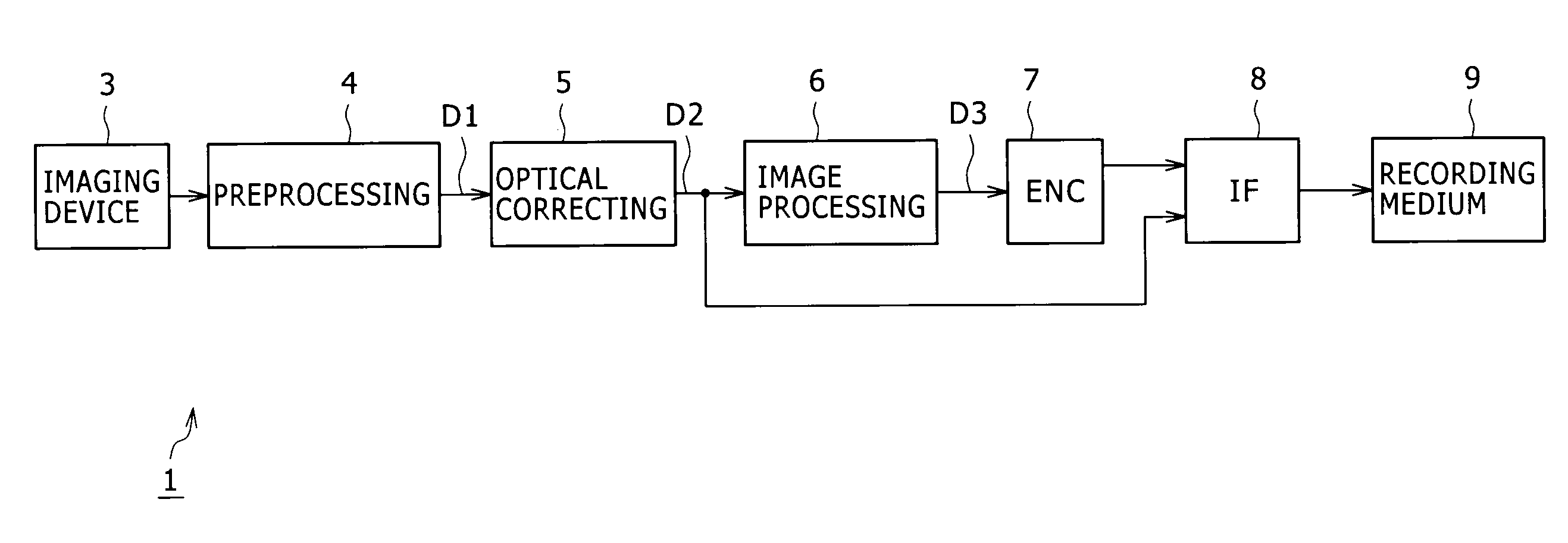
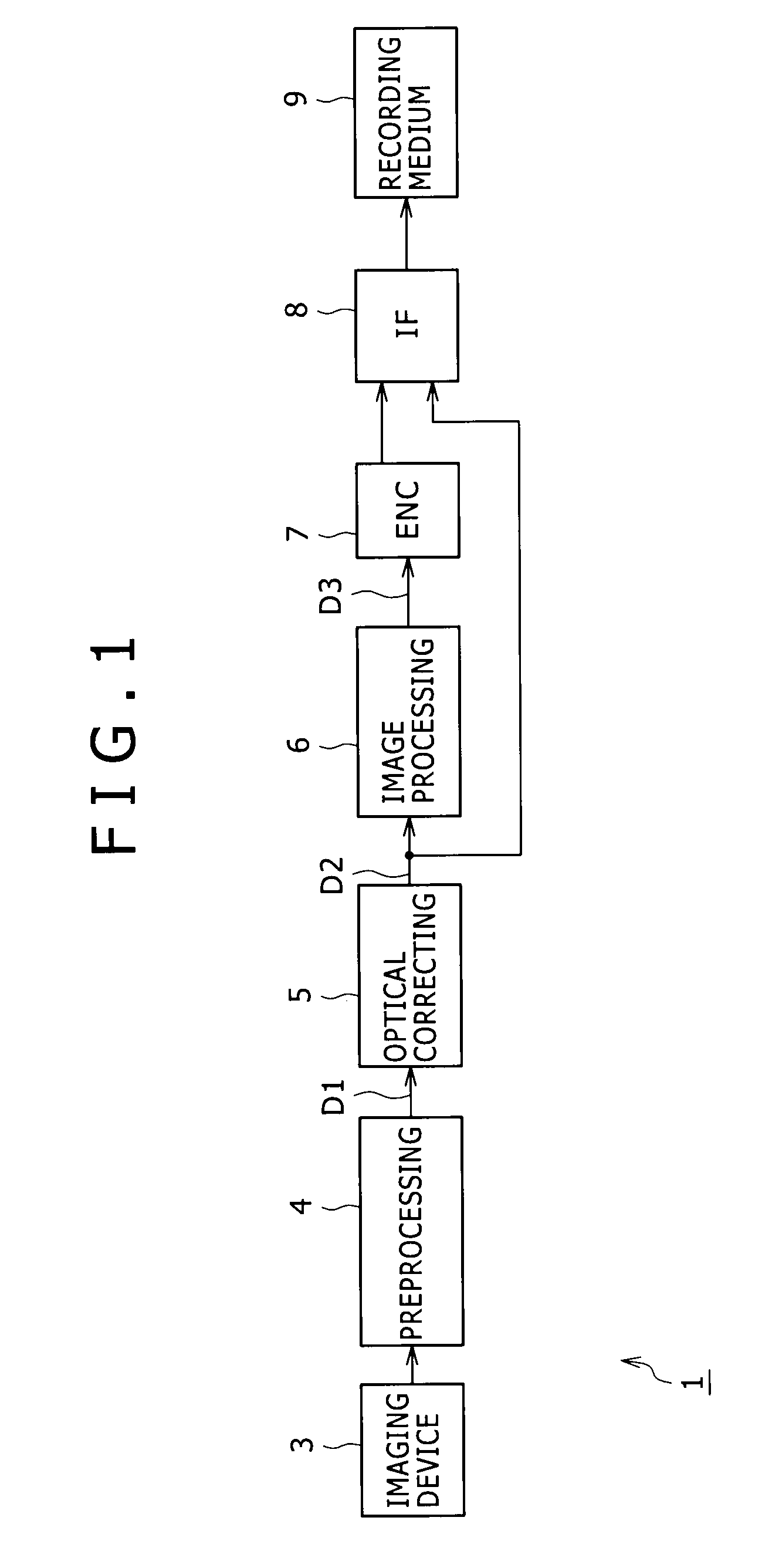
[0067]In the digital still camera 1 (FIG. 1) configured as described above, an image capture signal of red-, blue-, and green pixel values serially and consecutively arranged in the sequential order corresponding to the Bayer array of the imaging device 3 is generated in the imaging device 3. Then, the image capture signal is digital-analog converted in the preprocessing section 4, whereby raw data D1 is generated. In the digital still camera 1, noise in this raw data D1 is depressed in the optical correcting section 5. Subsequently, in the following image processing section 6, raw data D2 is subjected to the demosaicing process thereby to generate full-color image data, and the full-color image data D3 is converted to image data D3 of luminance signals and color difference signals. Then, the image data D3 is compressed by the encoder 7 and is then recorded onto the recording medium 9. Also, when a user has specified raw data recording, the raw data ...

second embodiment

(4) Second Embodiment

[0080]In a second embodiment, the median value of neighbor green pixels is adapted for the green pixel values Gx and Gy, which respectively are used as the processing references. A digital still camera of the second embodiment has the same configuration as the digital still camera 1 of the first embodiment described above, except that the configuration related to the generation for the processing reference pixel values is different therefrom.

[0081]More specifically, according to the second embodiment, as shown in FIG. 3, for the red pixel R2, the simple demosaicing section 15 sorts the pixel values of the green pixels Gb0, Gr2, Gr3, and Gb2 adjacent to the red pixel R2 in order of low pixel values thereof, and then calculates an average value of the second and third pixel values in the sorted order. The simple demosaicing section 15 sets the average value as the median value to the pixel values of green pixels in the position of the red pixel R2. Also, similarly...

third embodiment

(5) Third Embodiment

[0084]In a third embodiment, assuming that the spatial positions of red pixels and blue pixels corresponding to the red pixels are identical to one another, green pixel values in the spatial positions of red and blue pixels are calculated. Further, the present embodiment has the same configuration as the respective embodiments described above, except that the calculation method is different therefrom.

[0085]More specifically, it is assumed that the Bayer array of the imaging device 3 is formed from repetitive two-by-two pixel blocks, and the arrangement of the two-by-two pixel blocks is configured as shown in FIG. 16(A). It is further assumed that the spatial positions of the respective red and blue pixels R and B in FIG. 14 are at the central position of the two-by-two pixel block shown by a point P. In accordance with the assumption, as shown in FIGS. 16(A) and 16(B), the simple demosaicing sections 15 and 18 set an average value of green pixels Gr and Gb of the...


PUM


Abstract

A method and apparatus to remove color noise included in raw data while effectively preventing image quality degradation. For Interest pixels serially set onto a mosaic image formed of raw data, conversion is executed into a pixel value for noise removal based on a processing reference pixel value having a unified color signal component in each interest pixel, noise is removed from the pixel value for noise removal, and the pixel value for noise removal with noise removed is converted into the source pixel value, whereby only color noise can be removed without affecting a luminance signal.

Description

BACKGROUND OF THE INVENTION[0001]1. Technical Field[0002]The present invention relates to an image capture apparatus, an image processing apparatus, an image processing method, a program for the image processing method, and a recording medium that records therein the program for the image processing method, which are adaptable to, for example, digital still cameras. According to the invention, a pixel value of each interest pixel is converted into a pixel value for noise removal based on a processing reference pixel value having a unified color signal component in each interest pixel to remove noise therefrom, and then the pixel value is reversely converted into the original pixel value to effectively prevent image quality degradation, whereby color noise included in raw data can be removed.[0003]2. Background Art[0004]In conventional digital still cameras, after raw data serially acquired in a pixel array of an imaging device is demosaiced and a full color image is generated thereb...

Claims


Application Information

Patent Timeline
IPC IPC(8): G06K9/40
CPCH04N5/217H04N2209/046H04N2101/00H04N9/045H04N23/81H04N23/843H04N25/134H04N23/12
Inventor MATSUSHITA, NOBUYUKINAKAJIMA, KENYAMADA, MIKIKO
Owner SONY CORP
Why Eureka
Try Eureka