Magnetic field measurement system and optical pumping magnetometer

a technology of magnetic field measurement and optical pumping magnetometer, which is applied in the direction of magnetic field measurement using superconductive devices, instruments, applications, etc., can solve the problems of system inability to use, low detection sensitivity of fluxgate magnetometer, and difficulty in detecting weak environment magnetic signals such as biomagnetism, etc., to reduce environmental magnetic noise, high conductivity, and high magnetic permeability

Active Publication Date: 2010-02-02
HITACHI HIGH-TECH CORP
View PDF5 Cites 77 Cited by
  • Summary
  • Abstract
  • Description
  • Claims
  • Application Information

AI Technical Summary

Benefits of technology

[0014]In view of the foregoing problems, in a magnetic field measurement system using an optical pumping magnetometer as a reference sensor, it is an object of the present invention to stabilize a static magnetic field B0 and an oscillating magnetic field BRF to be applied to a vapor cell by reducing environmental magnetic noise that enters the optical pumping magnetometer without using a magnetic shield room, to prevent the oscillating magnetic field BRF from constituting an error signal in a biomagnetic signal and from affecting operation of a SQUID magnetometer, and to avoid an adverse effect of the oscillating magnetic field BRF to a pacemaker.
[0031]Moreover, according to the present invention, in a multichannel optical pumping magnetometer configured by combining a plurality of optical pumping magnetometers, it is possible not only to suppress environmental magnetic noise that enters each of vapor cells but also to prevent interference among oscillating magnetic fields applied to the respective vapor cells and to accurately and stably detect magnetism from a measurement object by each channel, by housing only magnetic detectors each configured of vapor cells, static magnetic field applying coils and RF coils in the magnetic shield cases, or by setting mutually different static magnetic field intensities to be applied to the respective vapor cells and adjusting the static magnetic field intensities to be applied to the respective vapor cells in order that a magnitude on the longitudinal axis at an intersection of each of optical magnetic resonance curves obtained by applying the oscillating magnetic fields to the individual vapor cells can be smaller than a half value of a peak of an optical magnetic resonance curve connecting the intersections. Moreover, it is possible to perform cardiac magnetic field measurement on a pacemaker-implanted patient, since leakage of the oscillating magnetic field to the heart can be suppressed by use of a magnetic shield case. Furthermore, when the multichannel optical pumping magnetometer is used as a substitute for a SQUID magnetometer for biomagnetic measurement, the multichannel optical pumping magnetometer does not require a coolant (liquid helium or liquid nitrogen) at all unlike the SQUID magnetometer. For this reason, it is possible to eliminate maintenance and running costs related to the coolant. Moreover, since the Dewar for preserving the coolant is unnecessary, it is possible to downsize the measurement system as compared to the conventional system using the SQUID magnetometer.

Problems solved by technology

In the case of the system combining the SQUID magnetometer and the fluxgate magnetometer, the fluxgate magnetometer is available at a low price but has low detection sensitivity.
Accordingly, the system can detect large environmental magnetic noise but has difficulty in detecting weak environment magnetic signals such as the biomagnetism.
Moreover, in the light of the detection sensitivity, there are problems that this system cannot be used inside the magnetic shield room that shields the environmental magnetic noise, and so on.
As a result, there arises a problem that the Dewar is virtually increased in size thereby the magnetic shield room for disposing the measurement system is also increased in size.
This poses problems in terms of operations and costs for its maintenance.
This makes the running costs and maintenance costs unnecessary.
Moreover, the oscillating magnetic field BRF which is indispensable for operating the optical pumping magnetometer has a risk of affecting operation of a cardiac pacemaker.
Accordingly, there is a problem when performing measurement of a cardiac magnetic field on a pacemaker-implanted patient undergoing a therapy for cardiac conduction disturbance or arrhythmia.
However, the operation of the optical pumping magnetometer causes the following problems.
Oscillating magnetic field components attributed to an RF coil used in the optical pumping magnetometer are included in biomagnetic signals to be measured with the SQUID magnetometer, and this hinders accurate biomagnetic measurement.
Moreover, the oscillating magnetic field component affects, as stray noise, voltage-current characteristics at a superconducting tunnel junction of the SQUID magnetometer, and the SQUID magnetometer fails to operate normally.
In addition, when operating the SQUID magnetometer and the optical pumping magnetometer without using the magnetic shield room, large environmental magnetic noise enters the vapor cell which serves as the magnetic detector of the optical pumping magnetometer.
This causes instability of the static magnetic field B0 and the oscillating magnetic field BRF to be applied to the vapor cell, and hinders accurate measurement of the environmental magnetic noise.
In the case of measuring the cardiac magnetic field, there is a risk that the oscillating magnetic field BRF affects the pacemaker, the risk being attributed to operation of the optical pumping magnetometer.

Method used


Image

  • Magnetic field measurement system and optical pumping magnetometer
  • Magnetic field measurement system and optical pumping magnetometer
  • Magnetic field measurement system and optical pumping magnetometer

Examples


Embodiment Construction

[0065]Hereinafter, embodiments of the present invention will be described with reference to the accompanying drawings.

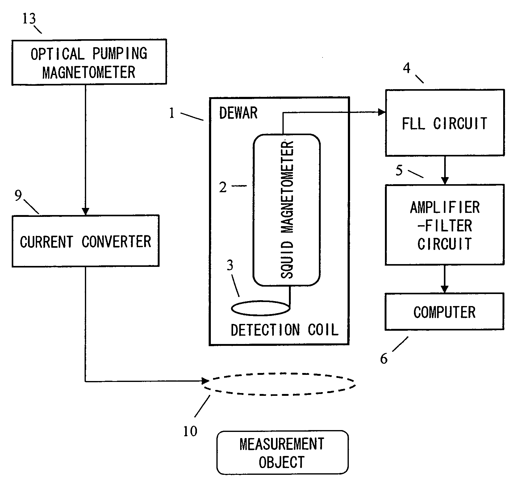
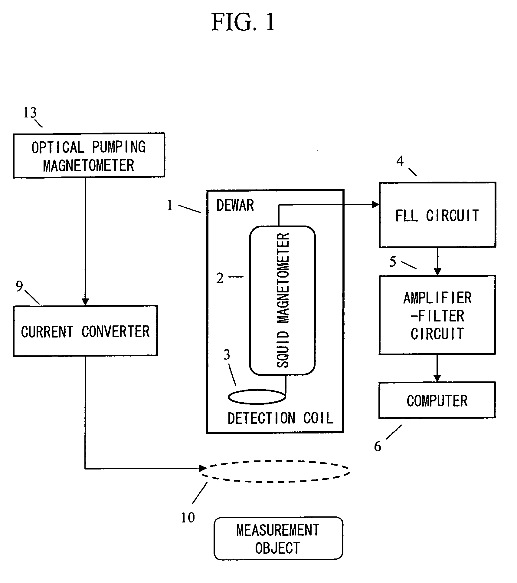
[0066]FIG. 1 is a diagram showing a configuration example of a biomagnetic measurement system of the present invention, in which a superconducting quantum interference device (SQUID) magnetometer 2 is used for biomagnetic measurement, and in which an optical pumping magnetometer 13 is used for environmental magnetic noise measurement.

[0067]A SQUID magnetometer 2 including a detection coil 3 is housed in a Dewar 1 filled with liquid helium (or liquid nitrogen). When measuring a biomagnetic signal from a measurement object with the SQUID magnetometer 2, environmental magnetic noise entering the SQUID magnetometer 2 is detected with an optical pumping magnetometer 13 which is disposed above the SQUID magnetometer 2. A signal detected with the optical pumping magnetometer 13 is converted into an amount of current by a current converter 9, and is transmitted to a magnetic...


PUM


Abstract

Provided is a highly accurate optical pumping magnetometer, in which a static magnetic field and an oscillating field to be applied to a vapor cell are stabilized. To this end, the optical pumping magnetometer includes: Helmholtz coils for applying a constant static magnetic field to a vapor cell serving as a magnetic field detector; fluxgate magnetometers for detecting environmental magnetic noise in two directions of X-axis direction and Y-axis direction other than Z-axis direction which is a direction for detecting a magnetic field coming out of a measurement object while locating the vapor cell in the center thereof; magnetometer drive circuits for driving the fluxgate magneotometers; current converters for converting outputs of the magnetometer drive circuits into amount of currents; and magnetic field generating coils for generating a magnetic field in a phase opposite to the environmental magnetic noise in the two directions.

Description

CLAIM OF PRIORITY[0001]The present application claims priority from Japanese applications JP 2005-342698 filed on Nov. 28, 2005 and JP 2006-138389 filed on May 18, 2006, the contents of which are hereby incorporated by reference into this application.BACKGROUND OF THE INVENTION[0002]1. Field of the Invention[0003]The present invention relates to a magnetic field measurement system and an optical pumping magnetometer, and more specifically to a magnetic field measurement system for measuring biomagnetism.[0004]2. Description of the Related Art[0005]When performing accurate biomagnetic measurement, it is essential to grasp the degree of environmental magnetic noise (such as geomagnetism or time-varying magnetism generated when an automobile or an electric train passes nearby) that hinder biomagnetic signal measurement. Conventional combinations of a magnetic sensor for biomagnetic measurement and a reference sensor for environmental magnetic measurement, which are used for highly accu...

Claims


Application Information

Patent Timeline
Patent Type & Authority Patents(United States)
IPC IPC(8): G01R33/035G01R33/02G01V3/00
CPCG01R33/0354G01R33/26Y10S505/846
Inventor KAWABATA, RYUUZOUKANDORI, AKIHIKO
Owner HITACHI HIGH-TECH CORP
Why Eureka
Try Eureka