Image pickup apparatus

Active Publication Date: 2016-01-07
CANON KK
View PDF4 Cites 12 Cited by
  • Summary
  • Abstract
  • Description
  • Claims
  • Application Information

AI Technical Summary

Benefits of technology

[0007]In view of foregoing, the invention provides an image pickup apparatus capable of holding a shield memb

Problems solved by technology

However, in the configuration of Japanese Patent Laid-open 2013-257486, using the LC filter increases power consumption of an image pickup apparatus with increasing power consumption of a smoothed circuit and decreases the number of photographable images of the image pickup apparatus.
Additi

Method used


Image

  • Image pickup apparatus
  • Image pickup apparatus
  • Image pickup apparatus

Examples


Embodiment Construction

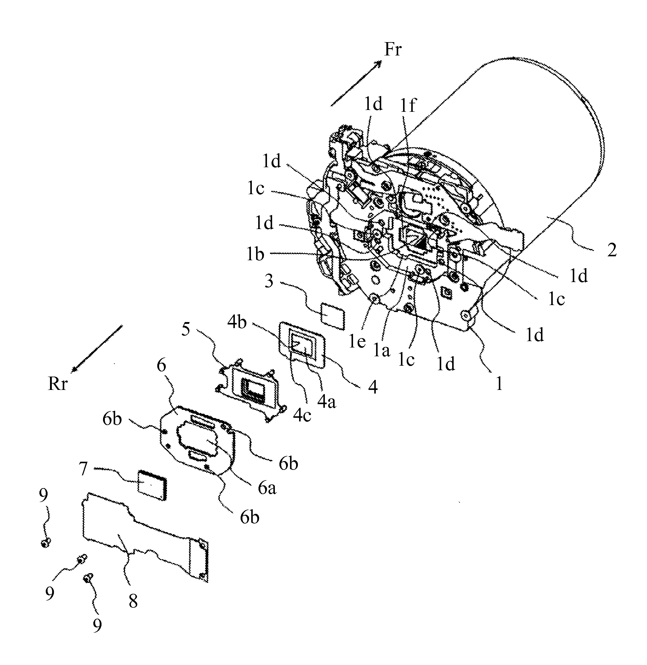
[0015]Exemplary embodiments of the invention will be described below with reference to the accompanied drawings. In each of the drawings, the same elements will be denoted by the same reference numerals and the duplicate descriptions thereof will be omitted. In this embodiment, a digital camera is described as one example of an image pickup apparatus. In each figure, a front direction Fr represents a front direction of the digital camera (direction close to an image pickup optical system) and a rear direction Rr represents a direction opposite to the front direction Fr (direction away from the image pickup optical system).

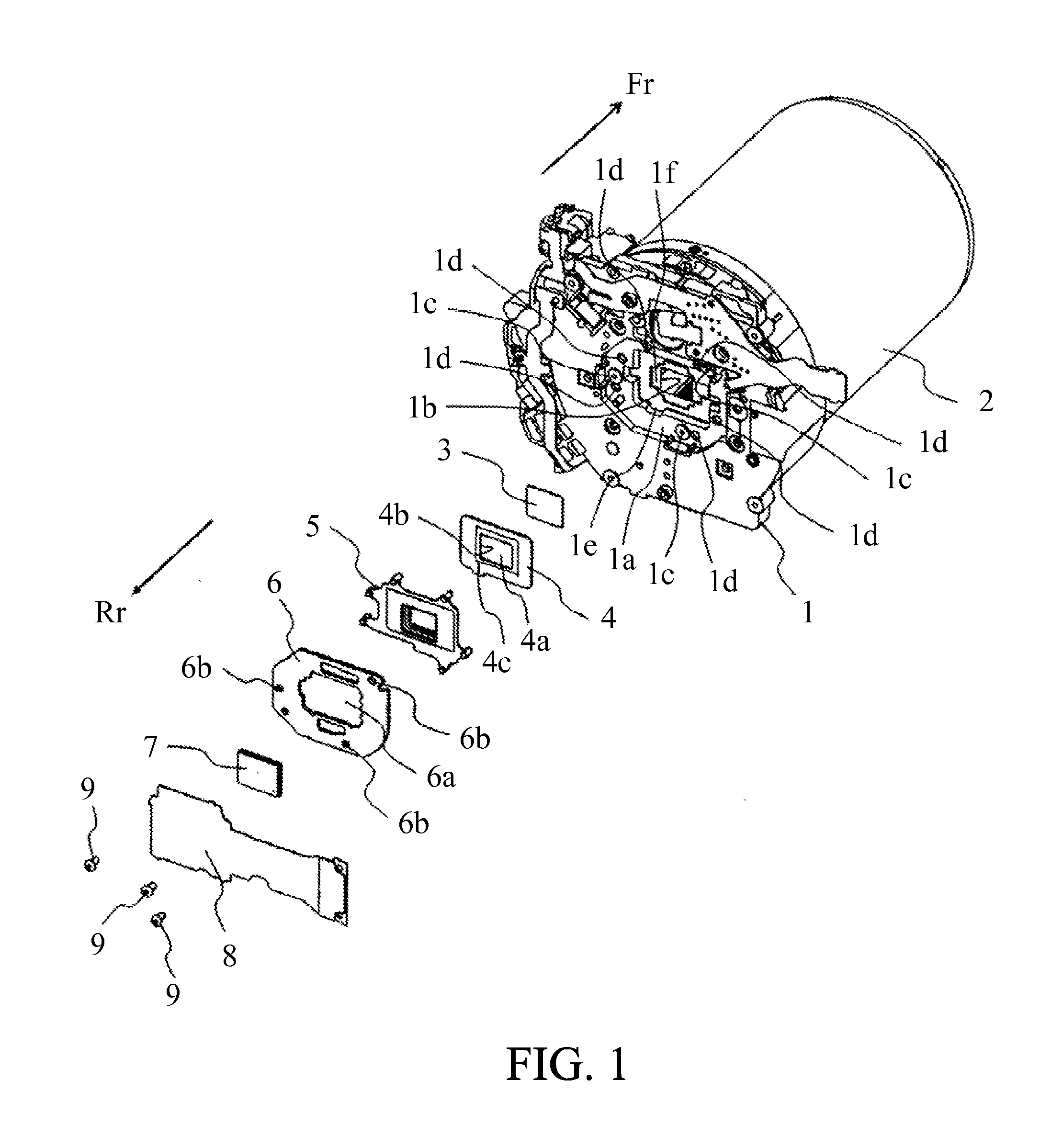
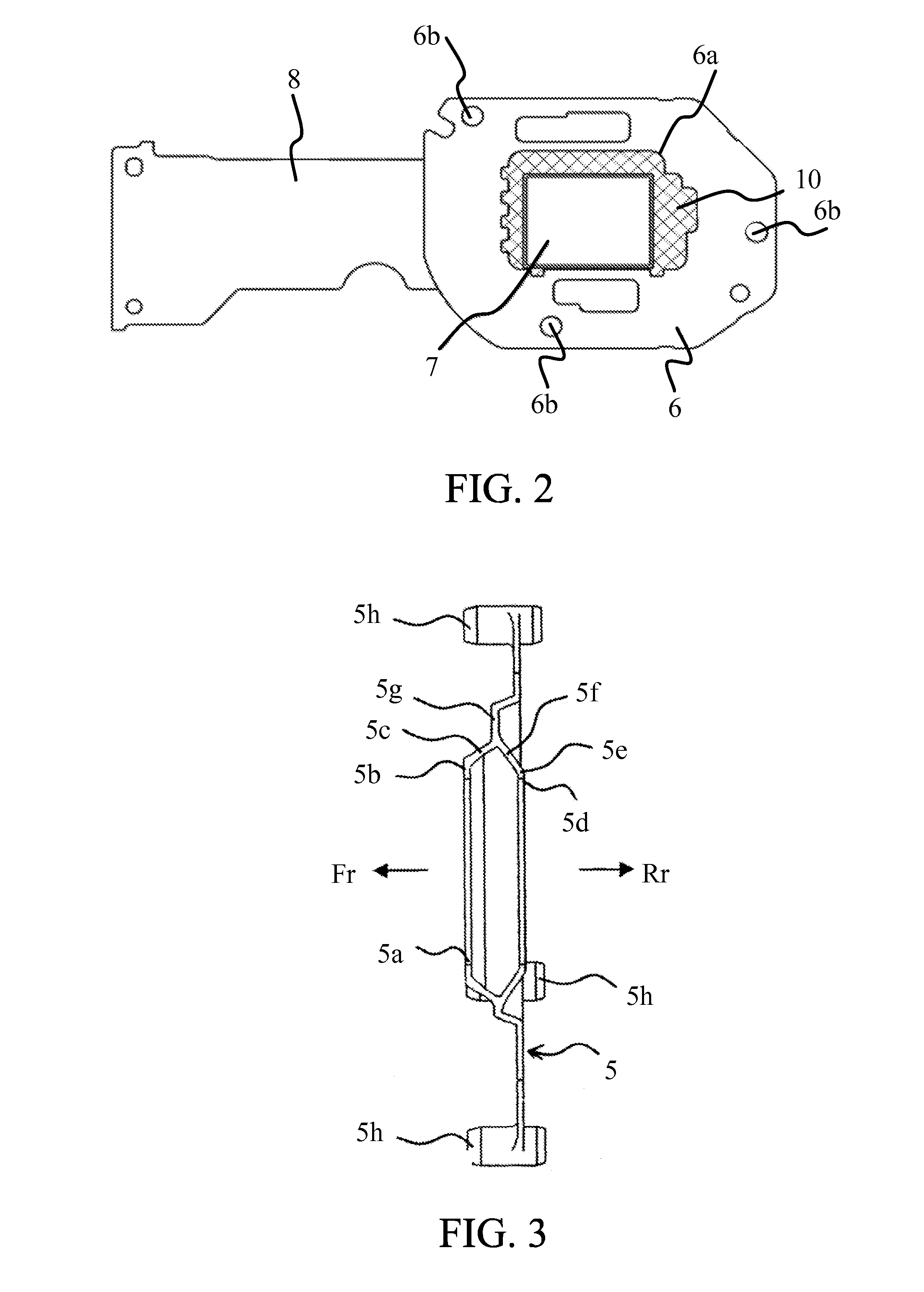
[0016]FIG. 1 is an exploded perspective view illustrating a part of components of the digital camera, and mainly illustrates components around an image pickup element. The digital camera includes a fixing base plate 1, a lens barrel 2, an optical filter 3, a magnetic shield plate 4, a dustproof rubber 5, a holding plate 6, an image pickup element 7, a flexible subs...


PUM


Abstract

An image pickup apparatus includes an image pickup element converting an object image to an electric signal, a magnetic shield member arranged in front of the image pickup element, a fixing member to which the image pickup element and the magnetic shield member are attached, and an elastic member arranged between the magnetic shield member and the image pickup element, and configured to press the image pickup element so as to surround a circumference of a light receiving plane of the image pickup element and to press the magnetic shield member toward the fixing member.

Description

BACKGROUND OF THE INVENTION[0001]1. Field of the Invention[0002]The invention relates to an image pickup apparatus that includes a magnetic shield member shielding a magnetic noise incident to an image pickup element.[0003]2. Description of the Related Art[0004]Higher fluctuation of a driving current while applying a current to a driving coil of an actuator, which drives an optical member, leads to higher fluctuation of a generated magnetic field. An influence of fluctuations of a magnetic field by the driving coil varies an image pickup signal of an image pickup element. In Japanese Patent Laid-open 2013-257486, using a LC filter smoothes current through a driving coil and reduces fluctuations of a current to decrease noises, such as horizontal lines, in an image output by a video signal processor. Japanese Patent Laid-open 2005-039691 discloses an image pickup apparatus that includes a shied member shielding a magnetic noise to an image pickup element.[0005]However, in the configu...

Claims


Application Information

Patent Timeline
IPC IPC(8): H04N5/357H04N5/369
CPCH04N5/369H04N5/3577H04N23/54
Inventor IWAMATSU, JUNICHIRO
Owner CANON KK
Why Eureka
Try Eureka