Rotary machine

a rotary machine and rotating shaft technology, applied in the direction of synchronous machines, windings, dynamo-electric components, etc., can solve the problems of inability to realize line manufacture, complex separation steps, and fear of the junction of retainers and conductors, so as to reduce the noise of magnetic components and reduce the high frequency components of electromotive force distribution.

Inactive Publication Date: 2005-09-08
HITACHI LTD
View PDF5 Cites 13 Cited by
  • Summary
  • Abstract
  • Description
  • Claims
  • Application Information

AI Technical Summary

Benefits of technology

[0024] The stator of the rotary machine of the present invention is characteristically multipoint-connected by the connection ring. When the conductor terminals are connected by the connection ring, there is no need to work on the conductor terminals such as notching. Further, when the connection ring is attached to the conductor terminals, the terminal position is fixed, so that the retainer for positioning the conductors is not required. When the conductor terminals are connected and the connection ring is separated, an armature winding is formed. In the aforementioned method, since the connection ring is connected, the sectional area of the joined part can be set to the sectional area of one conductor or more. The connection method can be executed by fusing, so that the terminals are separated on two surfaces and can be connected. Further, the joined part is not fused, so that there is no need to use expensive non-oxygen copper and ordinary tough pitch copper can be used.
[0025] In another stator of the rotary machine of the present invention, the high frequency component included in the electromotive force distribution can be reduced and the magnetic noise can be reduced. Further, the aforementioned stator of the rotary machine is characterized in consideration of the producibility and process simplification.

Problems solved by technology

When the input heat is high, there is a fear of junction of the retainers and conductors.
However, a step of notching the terminals after cutting the conductors in a fixed size or forming them in a U shape is necessary and line manufacture cannot be realized.
Further, to fuse the terminals by TIG, they must be separated on the four surfaces (all the surfaces) and the separation step is complicated.
Further, since the terminals are fused, the neighborhood of junction may be made fragile due to the hot shortness, so that as a conductor material, expensive non-oxygen copper must be adopted.
The high frequency component causes an increase in magnetic noise.
However, by use of the aforementioned winding constitution, arrangement of the conductors in the neighboring slots complicatedly increases the conductor kinds and in correspondence to it, a problem arises that the manufacturing steps are complicated.

Method used


Image

  • Rotary machine
  • Rotary machine
  • Rotary machine

Examples


embodiment 1

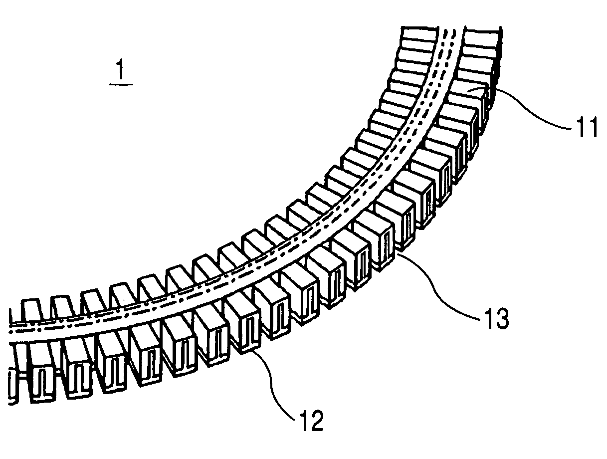
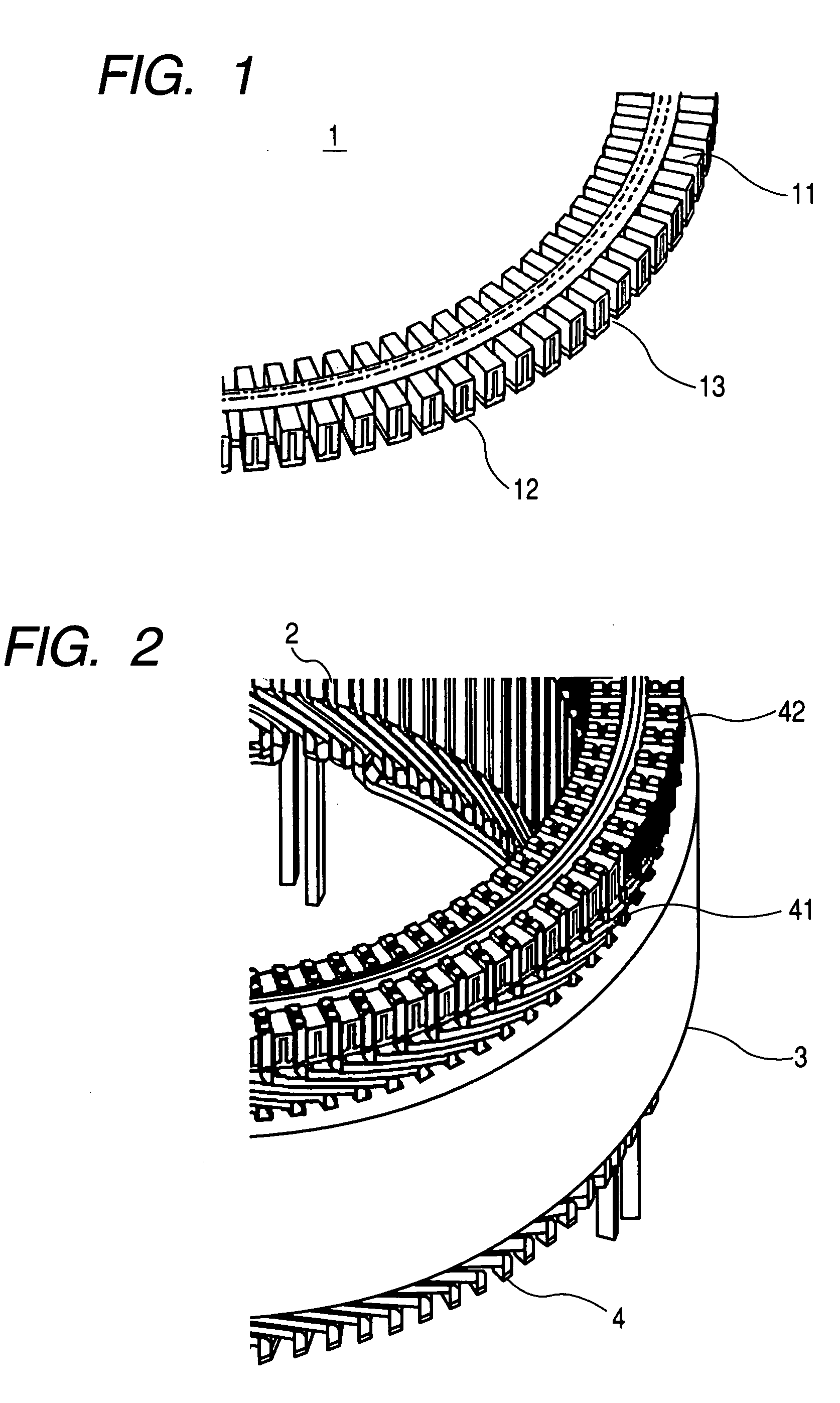
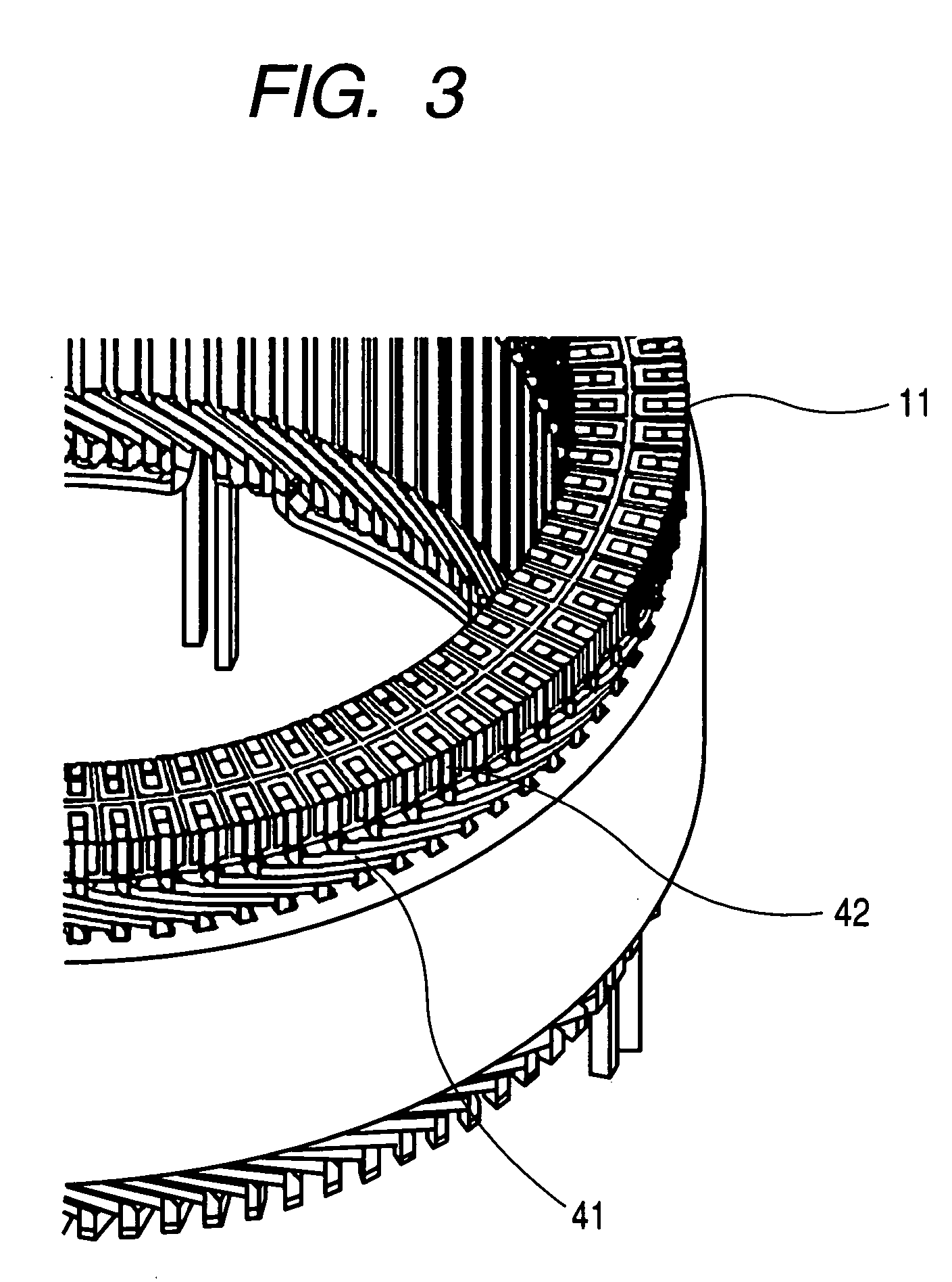
[0051] Embodiment 1 will be explained below. FIG. 1 shows an enlarged view of the connection ring used in this embodiment, and FIG. 2 shows an enlarged view of the connection ring attached status, and FIG. 3 shows an enlarged view of the status of the connection ring after division, and FIG. 4 shows a status diagram of the connection ring after division. FIGS. 1 to 4 show an example that the number of slots is 90 and 4 conductors are arranged in each slot.

[0052] In FIG. 1, a connection ring 1 is composed of a conductor portion 11 and an insulating portion 12. The connection ring 1 has a plurality of slots 13 corresponding to the number of connection points of a terminal portion 42 of a plurality of conductors 41, and between the plurality of slots 13 and the plurality of neighboring slots 13, the insulating portion 12 is arranged, thus uniform insulation is obtained. Four conductors are arranged in each slot, so that with respect to the terminal portion 42, from the outer periphera...

embodiment 2

[0054] Embodiment 2 will be explained below. FIG. 5 is an enlarged view of the status that reversely twisted conductors are connected and shows an example that the number of slots is 90 and 4 conductors are arranged in each slot. Four conductors are arranged in each slot, so that the phase winding is formed by an outside circuit 6 composed of a plurality of first and second conductors 41 from the outer peripheral side and an inside circuit 7 composed of a plurality of third and fourth conductors 41 and is formed by connecting a conductor 46 at the winding end of the outside circuit and a conductor 48 at the winding start of the inside circuit. The connection of the conductor 46 at the winding end of the outside circuit and the conductor 48 at the winding start of the inside circuit can be abolished by use of reversely twisted conductors 43.

embodiment 3

[0055] Embodiment 3 will be explained below. FIG. 6 is an enlarged view of the status that the conductors having a different spanning width are connected and shows an example of a winding circuit in which the number of magnetic poles is 12, and the number of slots is 90, and the number of phases of the stator winding is 3, and the number of slots per pole and per phase which is decided from the number of poles is 2.5, and one magnetic pole is composed of 5 conductors, and 4 conductors are arranged in each slot.

[0056] In the winding circuit, four conductors are arranged in each slot in a row in the radial direction, and the conductors are divided into the first and second conductors and the third and fourth conductors from the outer peripheral side, and the outside circuit 6 composed of the first and second conductors of the plurality of slots and the inside circuit 7 composed of the third and fourth conductors thereof are combined.

[0057] In the outside circuit 6 mentioned above, p...


PUM


Abstract

A rotary machine comprising a stator 2 composed of a stator iron core 3 having a plurality of slots formed in the direction of the rotation axis and stator windings inserted into the plurality of slots, wherein the stator windings are composed of a plurality of conductors 4 respectively inserted into the plurality of slots in the direction of the rotation axis and the stator 2 has a connection ring 1 having slots 13 into which the plurality of conductors 4 are inserted in the direction of the rotation axis.

Description

CLAIM OF PRIORITY [0001] The present application claims priority from Japanese application serial no. 2004-057167, filed on Mar. 2, 2004, the content of which is hereby incorporated by reference into this application. BACKGROUND OF THE INVENTION [0002] The present invention relates to a stator of a rotary machine and more particularly of a rotary machine of an AC generator for vehicle for generating power by being driven by an internal combustion engine and supplying power to a mobile electric load and a mobile power source. DESCRIPTION OF THE RELATED ART [0003] Conventionally, with respect to connection of a conductor terminal of a stator of a rotary machine, for example, Patent Document 1(Japanese Patent No. 3201397) and Patent Document 2(Japanese Patent No. 3303854) are known. In Patent Document 1, between two conductor terminals neighboring in the peripheral direction, a retainer is arranged in contact with the conductor terminals on both sides to retain the conductor terminals....

Claims


Application Information

Patent Timeline
Patent Type & Authority Applications(United States)
IPC IPC(8): H02K3/04H02K3/12H02K3/28H02K3/38H02K3/46H02K3/50
CPCH02K3/12H02K3/50H02K2203/09
Inventor MORI, YOSHIMIUEDA, TOSHIAKISAKAI, TAKESHIKIMURA, YASUHIKOONOSE, SHINKANAZAWA, HIROSHIHONMA, MASAHIKO
Owner HITACHI LTD
Why Eureka
Try Eureka