

Nanogranular thin film and magnetic recording media
- Summary
- Abstract
- Description
- Claims
- Application Information
AI Technical Summary
Benefits of technology
Problems solved by technology
Method used
Image

Examples
example 1
A (Fe.sub.aCo.sub.1-a).sub.1-x-Pt.sub.x-Based Nanogranular Thin Film
[0025] The Fe(Fe.sub.aPt.sub.1-a).sub.1-x-Pt.sub.x-based nanogranular thin film was deposited on a glass substrate and Si wafer by means of a dual target ion-beam sputtering machine. The final base pressure was 4.times.10.sup.-5 Pa or less, and the ion-beam accelerating voltage was 500 V. The target used to be sputtered for forming the magnetic material is a composite target consisting of an Fe target and Co and Pt chips symmetrically arranged on the Fe target. The Al, Ag or MgF.sub.2 targets were used to be sputtered for forming the Al, Ag or MgF.sub.2 matrix, respectively. In the case of Al.sub.2O.sub.3 and AlN matrix, oxygen or nitrogen was supplied in the vicinity of the substrates during the deposition.
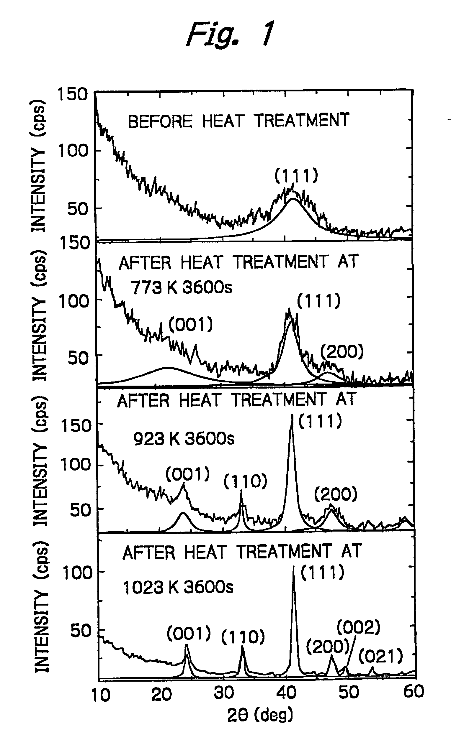
[0026] Referring to FIG. 1, the X-ray diffraction pattern of (Fe.sub.0.55Pt.sub.0.45).sub.0.47-(Al.sub.0.4O.sub.0.6).sub.0.53 granular thin film is shown. Since almost no ordering of the FePt phase occurs at a he...
example 2
[0030] The ((FeCo)Pt)--(AlO), ((FeCo)Pt)--(AlN), and ((FeCo)Pt)--(MgF) nanogranular films were prepared by the method of Example 1. The heat-treating temperature, coercive force, remanence and diameter of granules D are shown in Table 1.
1TABLE 1 Heat-Treating Time Coercive Residual Magnetization Diameter of Composition and Temperature Force Hc 4 .pi.Mr Granules D ((Fe.sub.0.8Co.sub.0.2).sub.0.57-Pt.sub.0.43).sub.0.55-(Al.sub.0.4O.sub.0.6).sub.0.45 923 K.3.6 Ks 650 kA / m 0.21 T 14 nm ((Fe.sub.0.8Co.sub.0.2).sub.0.56Pt.sub.0.44).sub.0.46--(Al.sub.0.4O.sub.0.6).sub.0.54 923 K.3.6 Ks 380 kA / m 0.19 T 8 m ((Fe.sub.0.8Co.sub.0.2).sub.0.57Pt.sub.0.43).sub.0.39-(Al.sub.0.4O.sub.0.-6).sub.0.61 923 K.3.6 Ks 200 kA / m 0.18 T 4 nm ((Fe.sub.0.4Co.sub.0.6).sub.0.54Pt.sub.0.46).sub.0.48-(Al.sub.0.4O.sub.0.-6).sub.0.52 923 K.3.6 Ks 310 kA / m 0.13 T 7 nm ((Fe.sub.0.3Co.sub.0.7).sub.0.53Pt.sub.0.47).sub.0.48-(Al.sub.0.4O.sub.0.-6).sub.0.52 923 K.3.6 Ks 280 kA / m 0.12 T 8 nm ((Fe.sub.0.9Co.sub.0.1).sub.0.5...
example 3
(Fe.sub.aCo.sub.1-a).sub.1-x-(Fe.sub.bPd.sub.1-b).sub.x-Based Nanogranular Thin Film
[0031] The (Fe.sub.aCo.sub.1-a).sub.1-x-(Fe.sub.bPd.sub.1-b).sub.x based nanogranular thin film was deposited on a glass substrate and Si wafer by means of a dual target ion-beam sputtering machine. The same method and conditions as in Example 1 were used in Example 3. The heat-treating temperature, coercive force, remanence and diameter of granules D are shown in Table 2.
2TABLE 2 Heat-Treating Time Coercive Residual Magnetization Diameter of Composition and Temperature Force Hc 4 .pi.Mr Granules D ((Fe.sub.0.8Co.sub.0.2).sub.0.57Pd.sub.0-.43).sub.0.55-(Al.sub.0.4O.sub.0.6).sub.0.45 923 K.3.6 Ks 180 kA / m 0.21 T 12 nm ((Fe.sub.0.8Co.sub.0.2).sub.0.56Pd.sub.0.44).sub.0.46-(Al.su-b.0.4O.sub.0.6).sub.0.54 923 K.3.6 Ks 155 kA / m 0.19 T 10 nm ((Fe.sub.0.8Co.sub.0.2).sub.0.57Pd.sub.0.43).sub.0.39-(Al.sub.0.4O.sub.0.-6).sub.0.61 923 K.3.6 Ks 121 kA / m 0.18 T 7 nm ((Fe.sub.0.9Co.sub.0.1).sub.0.54(Pt.sub.0.9Pd.s...
PUM
| Property | Measurement | Unit |
|---|---|---|
| Percent by atom | aaaaa | aaaaa |
| Percent by atom | aaaaa | aaaaa |
| Percent by atom | aaaaa | aaaaa |
Abstract
Description
Claims
Application Information