Dual lever steering control mechanism

a control mechanism and lever technology, applied in the direction of mechanical control devices, machine control, instruments, etc., can solve the problems of not being able to adjust the height of the control lever and the position of the lever, and the control levers or sticks cannot be readily sized or mounted to optimize so as to achieve the effect of optimizing the comfort of the operator

Active Publication Date: 2008-12-02
DEERE & CO
View PDF14 Cites 39 Cited by
  • Summary
  • Abstract
  • Description
  • Claims
  • Application Information

AI Technical Summary

Benefits of technology

[0007]A dual lever steering control mechanism is provided for mounting control levers or sticks to a ZTR mower. The dual lever steering control mechanism may be used interchangeably to mount either the left hand or right hand control lever or stick, and includes only four cast parts. The mechanism allows adjustment of the lever or stick to change its height setting and position relative to the operator seat or platform, to optimize operator comfort.

Problems solved by technology

Additionally, the control levers or sticks could not be readily sized or mounted to optimize operator comfort.
For example, ZTR mowers did not allow adjustment of the height of the control levers and the position of the levers relative to the operator seat or platform.

Method used


Image

  • Dual lever steering control mechanism
  • Dual lever steering control mechanism
  • Dual lever steering control mechanism

Examples


Embodiment Construction

[0012]The present invention may be used with a ZTR mower having at least one drive wheel on each side that is independently powered so that it may rotate independently of the other drive wheel. Each independent drive may include a separate hydrostatic drive motor coupled to each wheel. The pair of drive motors may be connected via hydraulic conduits to a dual hydrostatic pump; i.e, a separate pump for each wheel. Each side of the dual hydrostatic pump may have a swashplate that may define a pump stroke between a neutral position and a full forward position.

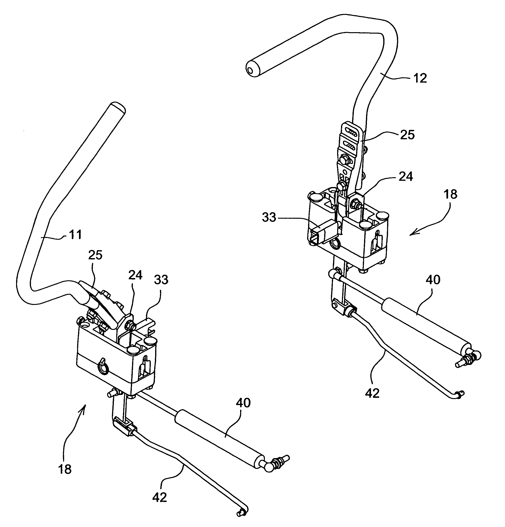
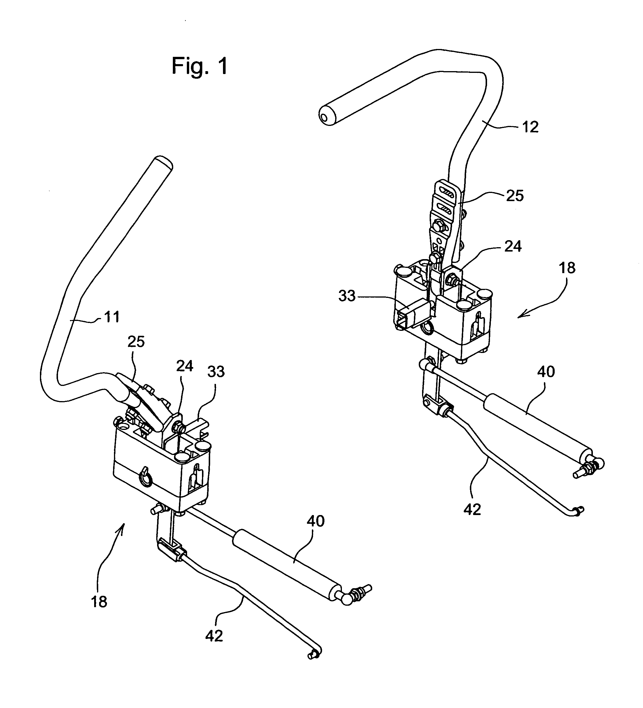
[0013]In a first embodiment shown in FIG. 1, left and right motion control levers or sticks 11, 12 may be used to operate a ZTR mower. Each control lever or stick may be mounted to the mower so that the lever may pivot forwardly to move a swashplate in a hydrostatic pump in a first direction to cause a drive wheel to rotate forward, or pivot rearwardly to move the swashplate in a second direction to cause the drive wheel to rotate...


PUM


Abstract

A dual lever steering control mechanism for a mounting a control lever or stick to a mower is disclosed. The mechanism includes a housing with an opening, a forward / reverse lever insertable through the opening and pivoting on a first axis, and a neutral position lever pivotably attached to the forward / reverse lever to pivot on a second axis transverse to the first axis. The control lever may be attached to the neutral position lever at a plurality of different height and fore / aft settings.

Description

FIELD OF THE INVENTION[0001]This invention relates to grass mowing machines, and specifically to zero turning radius (ZTR) mowing machines having independently powered left and right drive wheels controlled by a pair of control levers or sticks.BACKGROUND OF THE INVENTION[0002]Grass mowing machines known as ZTR mowers have at least one independently powered drive wheel on each side of a frame. One drive wheel may be operated in a forward direction while the other drive wheel may be stopped or operated in reverse. Many ZTR mowers have a twin stick control system. A pair of control levers or sticks may be provided side-by-side, with each lever or stick controlling one of the drive wheels. When both levers or sticks are advanced together forwardly out of their neutral position, both drive wheels rotate forwardly to cause the mower to move forward. A ZTR mower may be steered by advancing one lever or stick more than the other.[0003]Typically, each control lever or stick on a ZTR mower m...

Claims


Application Information

Patent Timeline
Patent Type & Authority Patents(United States)
IPC IPC(8): B62D11/24
CPCA01D34/68A01D2034/6843Y10T74/20104Y10T74/2003A01D2101/00A01D34/66
Inventor MAYER, BENJAMIN S.RESSLER, KYLE THOMAS
Owner DEERE & CO
Why Eureka
Try Eureka