Heat sink assembly

a technology for heat sinks and components, applied in the direction of electrical apparatus casings/cabinets/drawers, instruments, semiconductor/solid-state device details, etc., can solve the problems of industry unaddressed, and achieve the effect of improving the heat sink performance and reducing the heat sink temperatur

Active Publication Date: 2009-07-28
ADVANCED THERMAL SOLUTION
View PDF16 Cites 8 Cited by
  • Summary
  • Abstract
  • Description
  • Claims
  • Application Information

AI Technical Summary

Benefits of technology

[0008]In another exemplary embodiment, the heat sink assembly includes a heat sink, a frame clip, and a spring clip. The heat sink has a base portion and a top fin portion. The frame clip has a top wall portion and a bottom wall portion. The top wall portion has a perimeter sized to receive the base portion of the heat sink and prevent horizontal motion of the heat sink. The bottom wall portion of the frame clip has a perimeter sized to receive a chip. The bottom wall portion also has an inwardly extending ridge with an inner ridge perimeter sized to fit over and removably couple to a heat producing device. The spring clip is removably coupled to the frame clip and rests against the heat sink. The spring clip has a spring bias sized to produce a vertical force pressing the heat sink against the heat producing device.

Problems solved by technology

Thus, a heretofore unaddressed need exists in the industry to address the aforementioned deficiencies and inadequacies.

Method used


Image

  • Heat sink assembly
  • Heat sink assembly
  • Heat sink assembly

Examples


Embodiment Construction

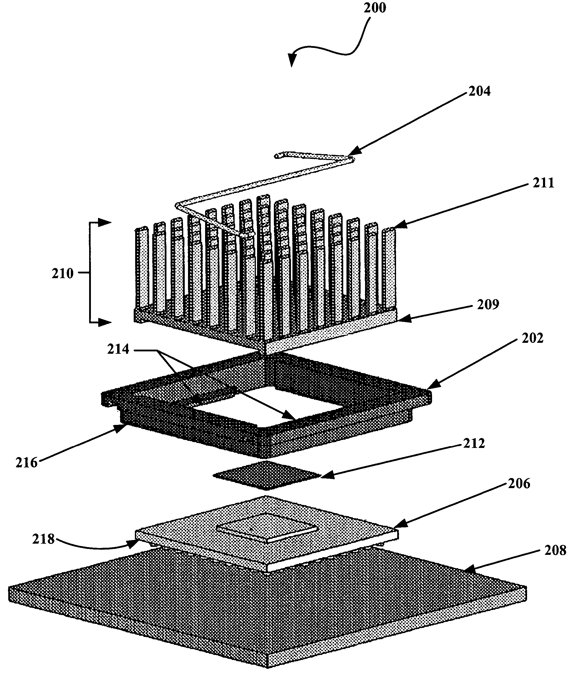
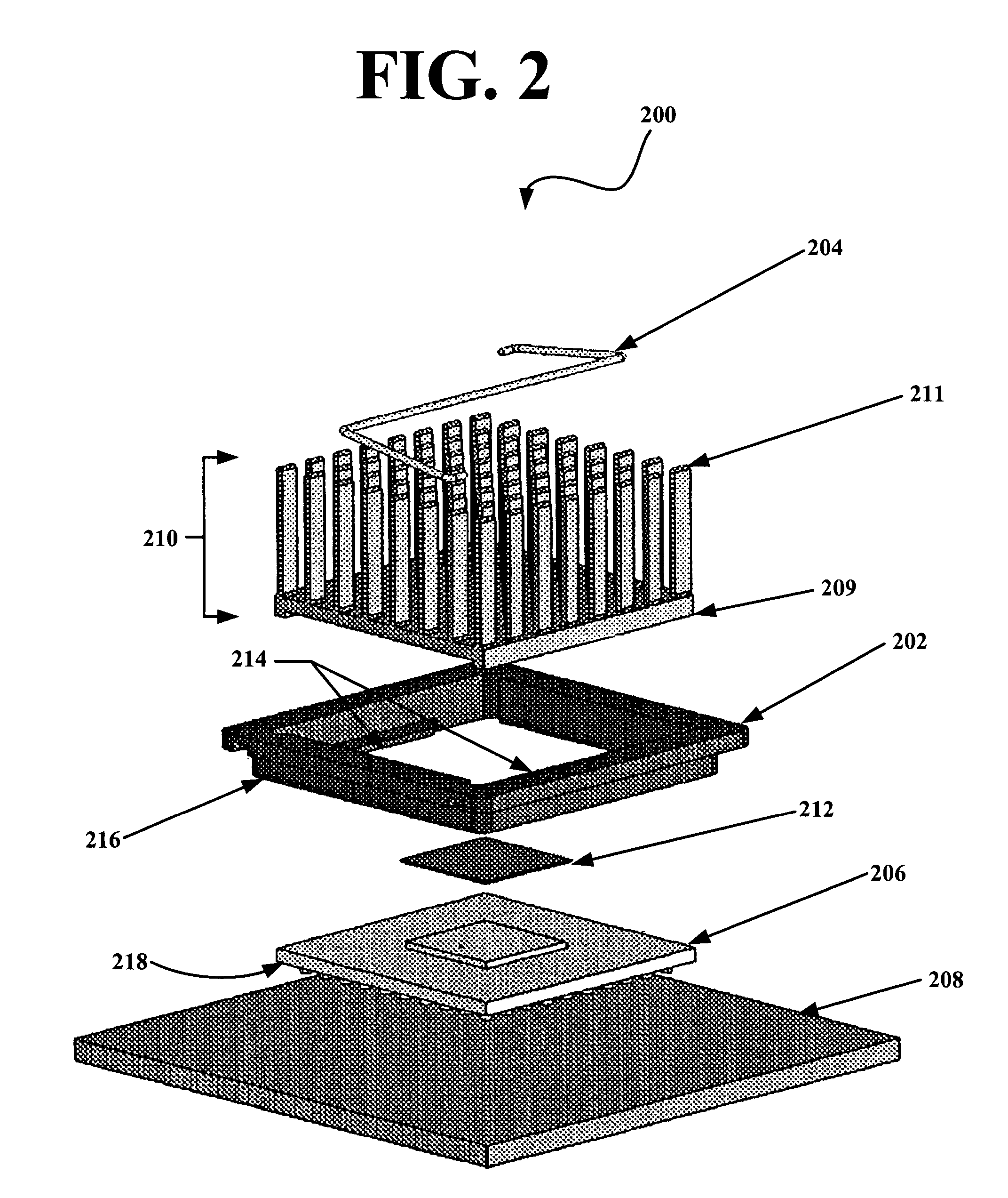
[0046]FIG. 2 and FIG. 3 are, respectively, an exploded and assembled perspective view of a heat sink assembly 200 in accordance with a first exemplary embodiment of the invention. The heat sink assembly 200 has a frame clip 202 and a spring clip 204. A heat producing device 206 can be coupled to a board 208, such as a printed circuit board, or other support structure. The board 208 can be, for example, but not limited to, a motherboard or other component that can be coupled to the heat producing device 206. The heat producing device 206 can be a variety of devices, for example, an integrated circuit or a variety of other optical or electrical components. A heat sink 210 is used to dissipate heat from the heat producing device 206. The heat sink 210 has a base 209 portion and a top fin 211 portion. Individual fins 211 may vary in length and individual fins 211 may be at varying angles with respect to the base 209. The heat sink 210 can be positioned against the heat producing device ...


PUM


Abstract

A heat sink assembly mount is provided. Generally the invention has a frame clip and a spring clip. The frame clip has one or more inwardly extending tabs and two or more vertically extending side portions. The one or more tabs are sized to fit over and removably couple to a heat producing device. The distance between the two or more vertically extending side portions is sized to hold a base portion of a heat sink and prevent horizontal motion of the heat sink. The spring clip couples to the frame clip and has a spring bias sized to produce a vertical force that presses the heat sink against a heat producing device.

Description

FIELD OF THE INVENTION[0001]The present invention is generally related to heat sinks, and more particularly is related to an assembly for a heat sink.BACKGROUND OF THE INVENTION[0002]Effective extraction of heat produced by electrical devices is important in order to extend the useful life of these devices. A conventional heat sink device typically utilizes an array of extended surfaces, such as fins, integrally formed on a common base and projecting into ambient fluid surrounding the device. The base is placed in thermally intimate contact with a heat producing device to provide a conduction path to the fin array. Fluid circulation, through forced or natural convection, around the fin array, acts as a heat transfer medium to cool the heat producing device to a satisfactory operating temperature.[0003]It is well recognized that various design parameters including fin geometry (e.g., the number of fins, fin spacing, and fin length and width), material selection, device characteristic...

Claims


Application Information

Patent Timeline
Patent Type & Authority Patents(United States)
IPC IPC(8): H05K5/00H05K7/00H05K7/20
CPCH01L23/4093H01L23/3672H01L23/3677H01L2924/0002H01L2924/00
Inventor AZAR, KAVEHMENNUCCI, JOSEPH P.MANDRONE, CARLO
Owner ADVANCED THERMAL SOLUTION
Why Eureka
Try Eureka