Power sensing eddy current resistance unit for an exercise device

a technology of eddy current resistance and power sensing, which is applied in the direction of frictional force resistors, gymnastic exercise, sport apparatus, etc., can solve the problems of high limiting the accuracy of systems of this type, and achieving the effect of accurately achieving the desired power outpu

Inactive Publication Date: 2009-09-08
SARIS CYCLING GROUP
View PDF18 Cites 69 Cited by
  • Summary
  • Abstract
  • Description
  • Claims
  • Application Information

AI Technical Summary

Benefits of technology

[0007]It is an object of the present invention to provide a rotating member resistance unit that includes the ability to control a user's power level in response to the degree of resistance applied to the rotating member. It is another object of the present invention to enable a user to monitor his or her own power output, and to control the applied resistance to provide a desired power output. Yet another object of the present invention is to provide control of the braking force that resists rotation of a rotating member in an exercise device resistance unit, regardless of the form of the braking mechanism. A further object of the invention is to measure and control the resistance applied to a rotating member in a resistance unit, which is used in combination with a desired power curve that may either be pre-programmed or inputted by the user, to enable a user to accurately achieve a desired power output.

Problems solved by technology

Systems of this type are functional but are highly inaccurate due to numerous variables that are involved in manufacture, assembly, engagement with the bicycle wheel (in the case of a bicycle trainer), and in operation of the power input system and the resistance unit.
The numerous variables significantly limit the accuracy of a system of this type.
Due to the numerous process variations and other variables as noted above, it has been found that systems of this type have accuracy limitations on the order of 15-20%.

Method used


Image

  • Power sensing eddy current resistance unit for an exercise device
  • Power sensing eddy current resistance unit for an exercise device
  • Power sensing eddy current resistance unit for an exercise device

Examples


Embodiment Construction

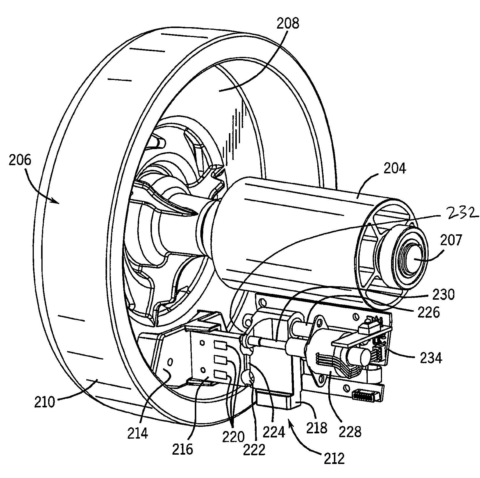
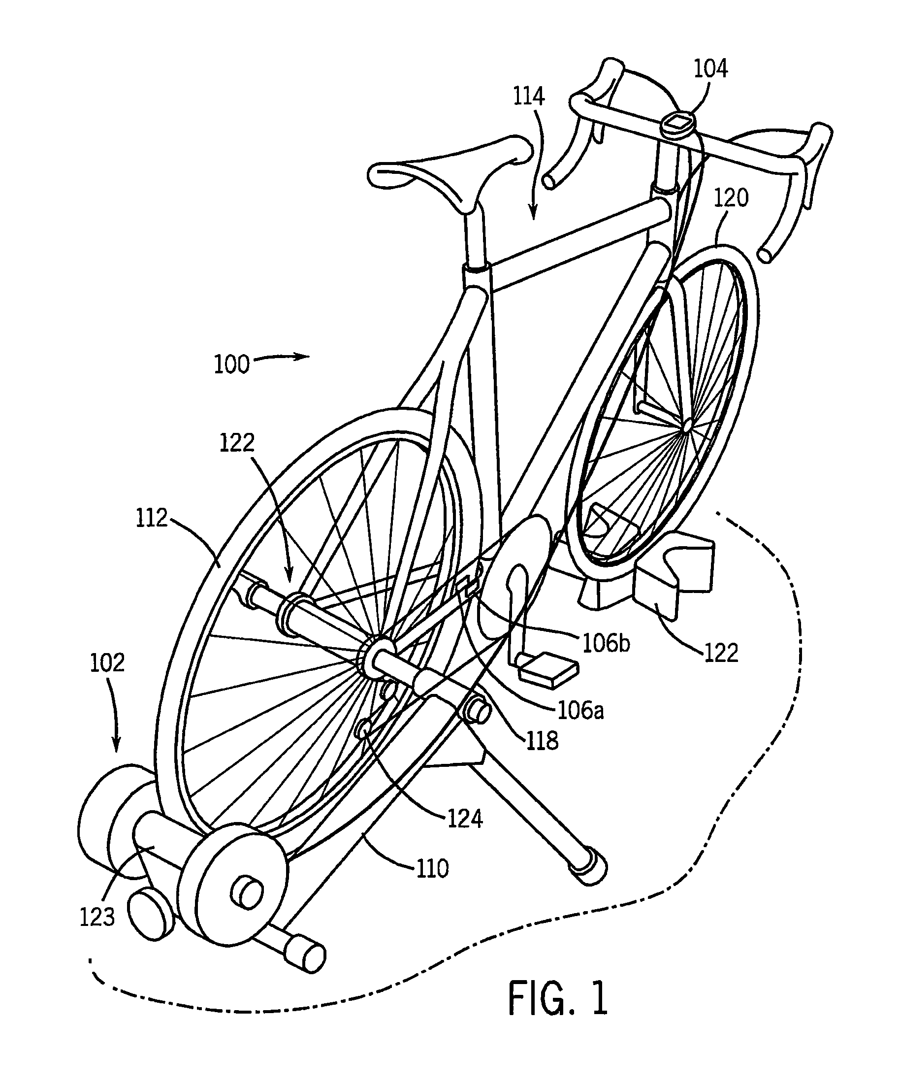
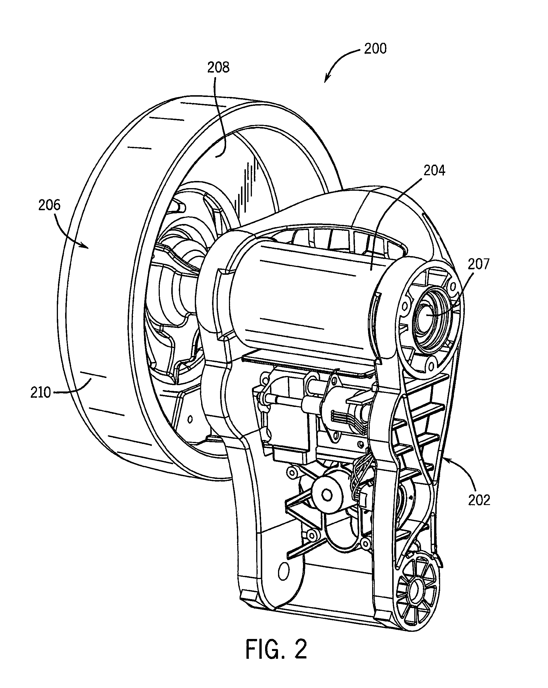
[0029]The present invention contemplates several embodiments of an exercise system or device. Each embodiment generally includes a rotating member, a resistance arrangement that either directly or indirectly resists rotation of the rotating member, a power input arrangement for causing rotation of the rotating member, a power sensing arrangement, and a resistance control that interacts with the resistance arrangement to set a resistance level based on the input power sensed by the power sensing arrangement.

[0030]In a first embodiment, an exercise system 100 includes a resistance unit 102 interconnected with a bicycle computer 104, which is mounted to a bicycle 114. Resistance unit 102 is held in position by a frame or support stand 110, which removably mounts a rear wheel 112 of bicycle 114, in a manner as is known. Bicycle trainers of this general type are available from Saris Cycling Group, Inc. of Madison, Wis. under its designation CycleOps.

[0031]Bicycle computer 104 and resista...


PUM


Abstract

An exercise system includes a user input arrangement; a rotatable member that rotates in response to an input force applied by a user on the user input arrangement; a power sensing arrangement that senses power applied to the rotatable member due to the input force applied by the user; and a variable resistance arrangement interconnected with the power sensing arrangement and with the user input arrangement. The resistance arrangement applies resistance to rotation of the rotatable member, and is variable in response to the power sensing arrangement to vary the resistance applied to the rotatable member. The variable resistance arrangement may be a brake that interacts with the rotatable member to resist rotation of the rotatable member, and to thereby resist the input force applied by the user. The variable resistance arrangement includes a controller for controlling the brake in response to the power sensing arrangement.

Description

CROSS-REFERENCE TO RELATED APPLICATION[0001]This application is a continuation of application Ser. No. 11 / 387,416 filed Mar. 23, 2006, which claims the benefit of provisional patent application Ser. No. 60 / 751,776 filed Dec. 20, 2005, and provisional patent application Ser. No. 60 / 664,343 filed Mar. 23, 2005, the disclosures of which are hereby incorporated by reference.BACKGROUND AND SUMMARY OF THE INVENTION[0002]This invention relates to an exercise device or system that incorporates a rotating member for resisting input forces applied by a user, and more particularly to a resistance control arrangement for use in such an exercise device or system.[0003]Many exercise devices utilize a rotating member that rotates in response to the application of input power by a user. In an exercise device of this type, it is common to provide resistance to rotation of the rotating member in order to provide resistance to the user. One example of an exercise device that incorporates a rotating me...

Claims


Application Information

Patent Timeline
Patent Type & Authority Patents(United States)
IPC IPC(8): A63B22/06A63B21/005A63B69/16A63B22/08A63B21/015
CPCA63B24/00A63B69/16A63B22/0605A63B21/0051A63B21/015A63B21/225A63B2024/0078Y10S482/903A63B2069/166A63B2069/168A63B2220/34A63B2220/54A63B2225/50A63B2069/164
Inventor WATSON, EDWARD M.WENDT, DAVID L.KOLDA, CLINT D.
Owner SARIS CYCLING GROUP
Why Eureka
Try Eureka