
Hook ring segment for a compressor vane
a compressor vane and hook ring technology, which is applied in the direction of machines/engines, liquid fuel engines, forging/pressing/hammering apparatus, etc., can solve the problems of limited damping, significant wear at the compressor vane attachment hooks and the circumferential area, and the arrangement is not ideal for engine operation. , to achieve the effect of improving the contact area between the hook ring and the compressor cas
- Summary
- Abstract
- Description
- Claims
- Application Information
AI Technical Summary
Benefits of technology
Problems solved by technology
Method used
Image

Examples
Embodiment Construction
[0022]The subject matter of the present invention is described with specificity herein to meet statutory requirements. However, the description itself is not intended to limit the scope of this patent. Rather, the inventors have contemplated that the claimed subject matter might also be embodied in other ways, to include different steps or combinations of steps similar to the ones described in this document, in conjunction with other present or future technologies. Moreover, although the terms “step” and / or “block” may be used herein to connote different elements of methods employed, the terms should not be interpreted as implying any particular order among or between various steps herein disclosed unless and except when the order of individual steps is explicitly described.
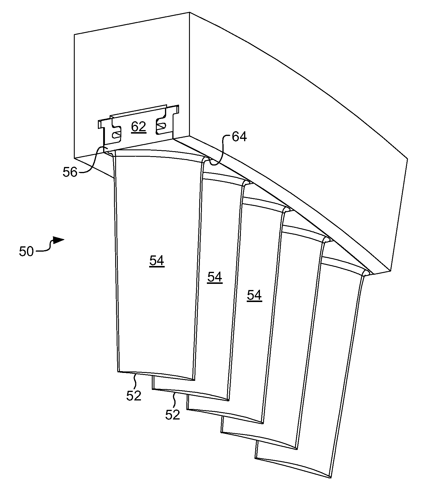
[0023]Referring now to FIGS. 4-7, the present invention provides a vane assembly 50 for reducing operating stresses and vibrations in individual vanes. The vane assembly of the present invention comprises a plura...
PUM
| Property | Measurement | Unit |
|---|---|---|
| angle | aaaaa | aaaaa |
| distance | aaaaa | aaaaa |
| circumferential length | aaaaa | aaaaa |
Abstract
Description
Claims
Application Information