Roller bearing retainer and needle roller bearing

a technology of roller bearing and retainer, which is applied in the direction of roller bearings, rotary machine parts, mechanical equipment, etc., can solve the problems of difficult to prevent the roller from dropping out, the play amount of the roller cannot be sufficiently provided, and the retainer of the roller could be easily damaged, so as to improve the oil lubrication property in a radial direction, reduce the contact surface pressure at the contact part, and prevent abrasion and burning at the wall surface

Active Publication Date: 2010-11-04
NTN CORP
View PDF7 Cites 12 Cited by
  • Summary
  • Abstract
  • Description
  • Claims
  • Application Information

AI Technical Summary

Benefits of technology

[0030]A needle roller bearing according to a preferred embodiment includes the retainer having any one of the characteristics described in the above, and a plurality of needle rollers contained in pockets of the retainer. The needle roller is in contact with the wall surface of the column part opposed to a rolling surface of the needle roller, over 50% or more of an effective length of the needle roller. Thus, when the contact area between the needle roller and the column part is increased, the contact surface pressure at the contact part can be reduced. As a result, the needle roller can be prevented from skewing and the abrasion and burning at the wall surface can be prevented. In addition, the “effective length of the needle roller” in this specification means the axial length of the needle roller except for the chamfered part at axial each end.
[0031]Preferably, the wall surface of the column part opposed to the rolling surface of the needle roller has a roller stopper part projecting from the wall surface, a non-contact part provided at the region radially adjacent to the roller stopper part so as to retreat from the wall surface and opposed to the needle roller with a predetermined clearance, and a guide surface brought in contact with the needle roller at the region axially adjacent to the roller stopper part. Thus, since the needle roller is in contact with the region axially adjacent to the roller stopper part, the contact area between the needle roller and the column part can be increased as compared with a conventional welded retainer in which the guide surface is provided at the region radially adjacent to the roller stopper part.
[0032]Further preferably, the wall surface of the column part opposed to the rolling surface of the needle roller has a recess part retreating from the non-contact part and extending in the radial direction, at axial each end of the roller stopper part. Thus, the oil lubrication property in a radial direction can be improved. According to one embodiment, the non-contact part is sloped such that the predetermined clearance is increased with the radial distance from the roller stopper part.
[0033]Further preferably, a pitch circle of the plurality of needle rollers is positioned on the radial inner side as compared with an outer diameter surface of the column center part, and positioned on the radial outer side as compared with an inner diameter surface of the column end part. Thus, the needle roller can be in contact with each of the column center part, the column end part, and the column sloped part. As a result, the contact area between the needle roller and the column part can be increased.

Problems solved by technology

Since stress applied to the retainer at the time of the rotation of the bearing concentrates on the bend part, the roller bearing retainer could be easily damaged because the bend part is thinned.
In addition, according to the roller bearing retainer disclosed in the above document, when the roller has a small diameter, it is difficult to prevent the roller from dropping out.
Meanwhile, when the circumferential interval between the adjacent column parts is reduced in order to prevent the roller from dropping out of the retainer for sure, the play amount of the roller cannot be sufficiently provided.

Method used


Image

  • Roller bearing retainer and needle roller bearing
  • Roller bearing retainer and needle roller bearing
  • Roller bearing retainer and needle roller bearing

Examples


Embodiment Construction

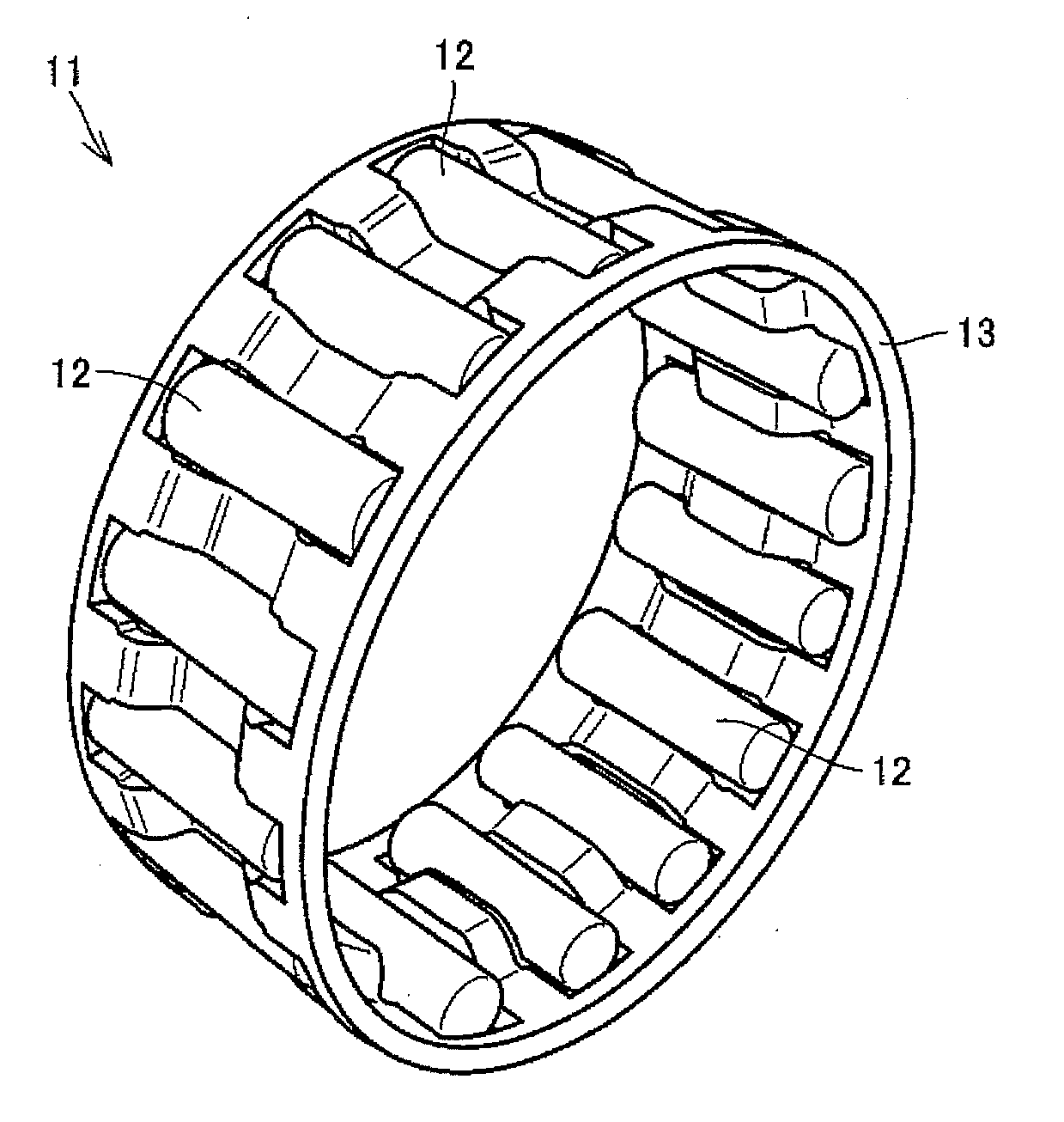
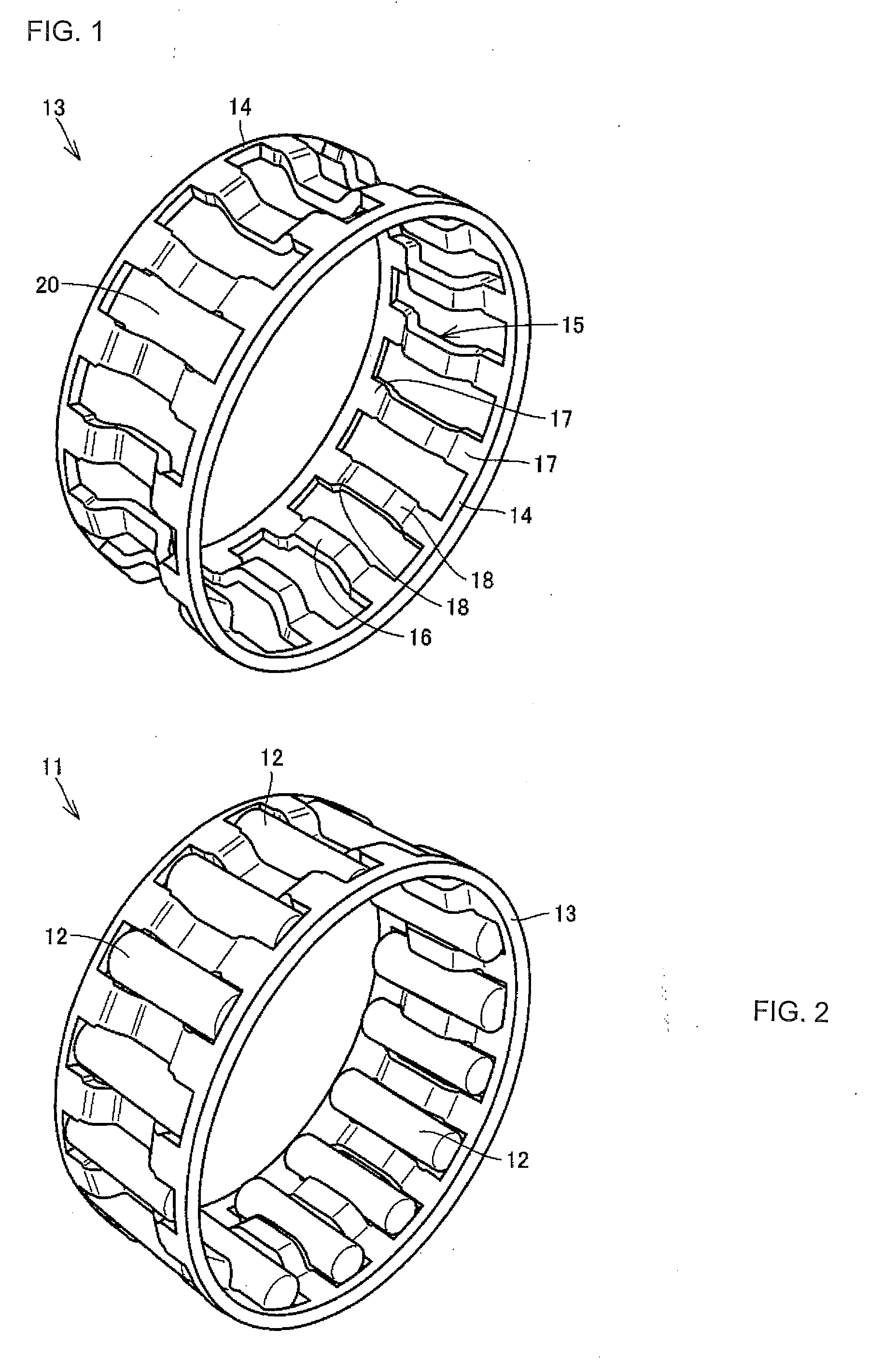
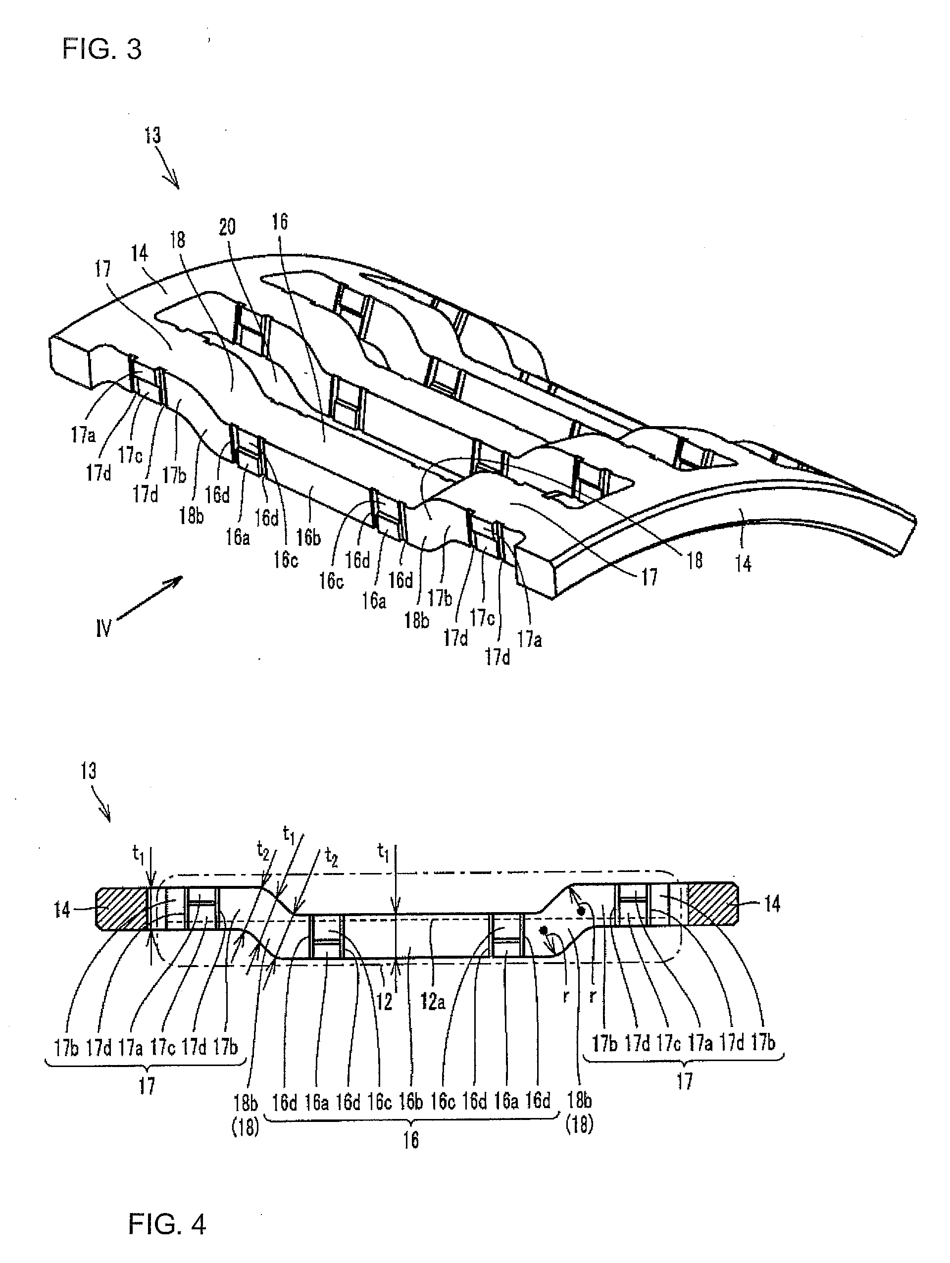
[0079]A description will be made of a needle roller bearing 11 and a roller bearing retainer 13 (referred to as the “retainer 13” simply hereinafter) according to one embodiment of the present invention, with reference to FIGS. 1 to 4. In addition, FIG. 1 is a perspective view showing the retainer 13, FIG. 2 is a perspective view showing the needle roller bearing 11, FIG. 3 is a perspective view showing a configuration of a column part 15 of the retainer 13, and FIG. 4 is a sectional view taken from a direction of an arrow IV in FIG. 3.

[0080]First, referring to FIG. 2, the needle roller bearing 11 includes a plurality of needle rollers 12, and the retainer 13 retaining the plurality of needle rollers 12. Next, referring to FIG. 1, the retainer 13 includes a pair of annular ring parts 14, and the plurality of column parts 15 connecting the pair of ring parts 14 to each other. In addition, a pocket 20 to hold the needle roller 12 is formed between the adjacent column parts 15.

[0081]In...


PUM

PropertyMeasurementUnit
outer diameteraaaaaaaaaa
surface roughnessaaaaaaaaaa

Abstract

A roller bearing retainer (13) includes a pair of annular ring parts (14) and a plurality of column parts (15) each including a column center part (16) provided in an axial center region so as to be positioned relatively on the radial inner side, a pair of column end parts (17) provided in axial end regions so as to be positioned relatively on the radial outer side, and a pair of column sloped parts (18) positioned between the column center part (16) and the pair of column end parts (17), and connecting the pair of ring parts to each other. A thickness of each part of the column center part, the pair of column end parts, and the pair of column sloped parts is smaller than a thickness of a boundary part between the adjacent parts.

Description

TECTHICAL FIELD[0001]The present invention relates to a roller bearing retainer produced by a pressing process, and a needle roller bearing including the roller bearing retainer.BACKGROUND ART[0002]A cage & roller type of needle roller bearing composed of rollers and a retainer is employed as an idler bearing of a car transmission, and a bearing for a connecting rod large end of a motorcycle engine in many cases. Such bearing is disclosed in Japanese Unexamined Patent Publication No. 2000-257638 (Patent Document 1), for example.[0003]According to this document, a pipe-shaped material is formed into an annular member having an M-shaped cross section by a bulging process, and pockets to hold rollers are formed in the annular member, whereby a roller bearing retainer light in weight and large in load capacity can be provided.[0004]The roller bearing retainer having the above constitution is guided on the outer diameter side in which a column end part and a housing are in contact with e...

Claims


Application Information

Patent Timeline
Patent Type & Authority Applications(United States)
IPC IPC(8): F16C33/48F16C19/44
CPCB21D53/12F16C19/46F16C33/54F16C33/546F16C2220/42F16C19/463F16C33/541F16C2220/84F16C33/543F16C2300/02
Inventor OISHI, SHINJIYOSHIMURA, YUGOABE, KATSUFUMI
Owner NTN CORP
Why Eureka
Try Eureka