Fixed constant-velocity universal joint

Active Publication Date: 2010-02-04
NTN CORP
View PDF4 Cites 11 Cited by
  • Summary
  • Abstract
  • Description
  • Claims
  • Application Information

AI Technical Summary

Benefits of technology

[0034]In the present invention, the rigidity of each cage window column can be increased. Therefore, large balls can be disposed in a small PCD. Size reduction can be achieved without reducing load capacity. Moreover, damage to the cage in relation to torsional torque at a high angle can be prevented. In addition, as a result of the long pockets being provided, mounting of the inner member to the cage can be facilitated. In particular, as a result of the axial direction length of the inner member being shorter than a shortest length of the circumferential direction spacing of the long pockets, the mounting of the inner member to the cage can be further facilitated, thereby improving mounting operability.
[0035]As a result of the projection being provided, the rigidity of the frames (window frames) used to form the pockets can be improved. As a result, deformation of the cage due to insufficient rigidity in the window frames can be prevented. Workability of the joint does not deteriorate. Stable workability can be achieved for a long period of time. Furthermore, as a result of the projection being provided, the contact area between the outer member and the inner member can be increased. Heat generation during sliding can be suppressed, and damage to the joint at an early stage can be prevented.
[0036]When the projection is provided on the long side on the joint opening side, the interference between the inner circumferential edge at the opening (entrance) of the outer member and the pocket edge on the cage outer spherical surface side can be delayed or prevented. When the projection is provided on the long side on the joint inner side, the interference between the inner edge of the outer spherical surface of the inner member and the pocket edge on the cage inner spherical surface side can be delayed or prevented. Therefore, guidance of the cage to the inner spherical surface of the outer member and the outer spherical surface of the inner member can be facilitated. Deter

Problems solved by technology

However, when large balls are used, columns (window columns) between the pockets in the cage become narrow.
Rigidity of the cage deteriorates.
Torsional torque load at a high angle particularly contributes to deterioration of strength of the constant velocity universal joint because damage to the cage occurs more easily.
In other words, the ball easily runs over a track edge in relation to the torque load at a high angle, generating excessive stress in an edge section.
Therefore, dama

Method used


Image

  • Fixed constant-velocity universal joint
  • Fixed constant-velocity universal joint
  • Fixed constant-velocity universal joint

Examples


Example

[0083]A basic embodiment of the present invention will be described hereafter with reference to FIG. 1 to FIG. 19. Three modified embodiments will thereafter be described with reference to FIG. 20 to FIG. 28, FIG. 29 to FIG. 30, and FIG. 31 to FIG. 40.

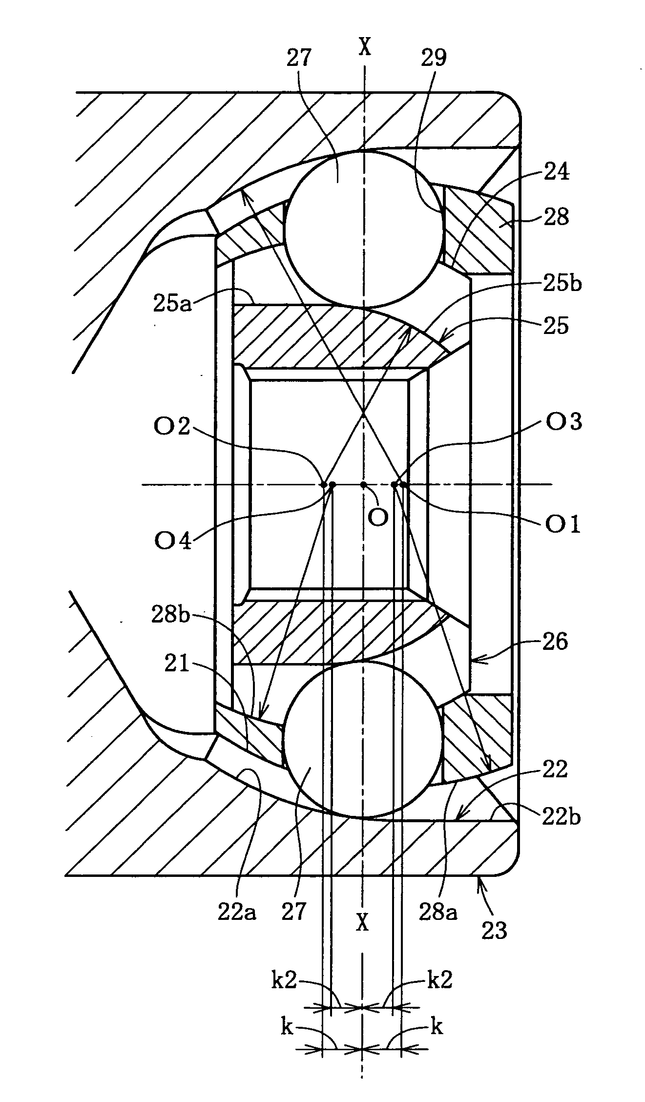
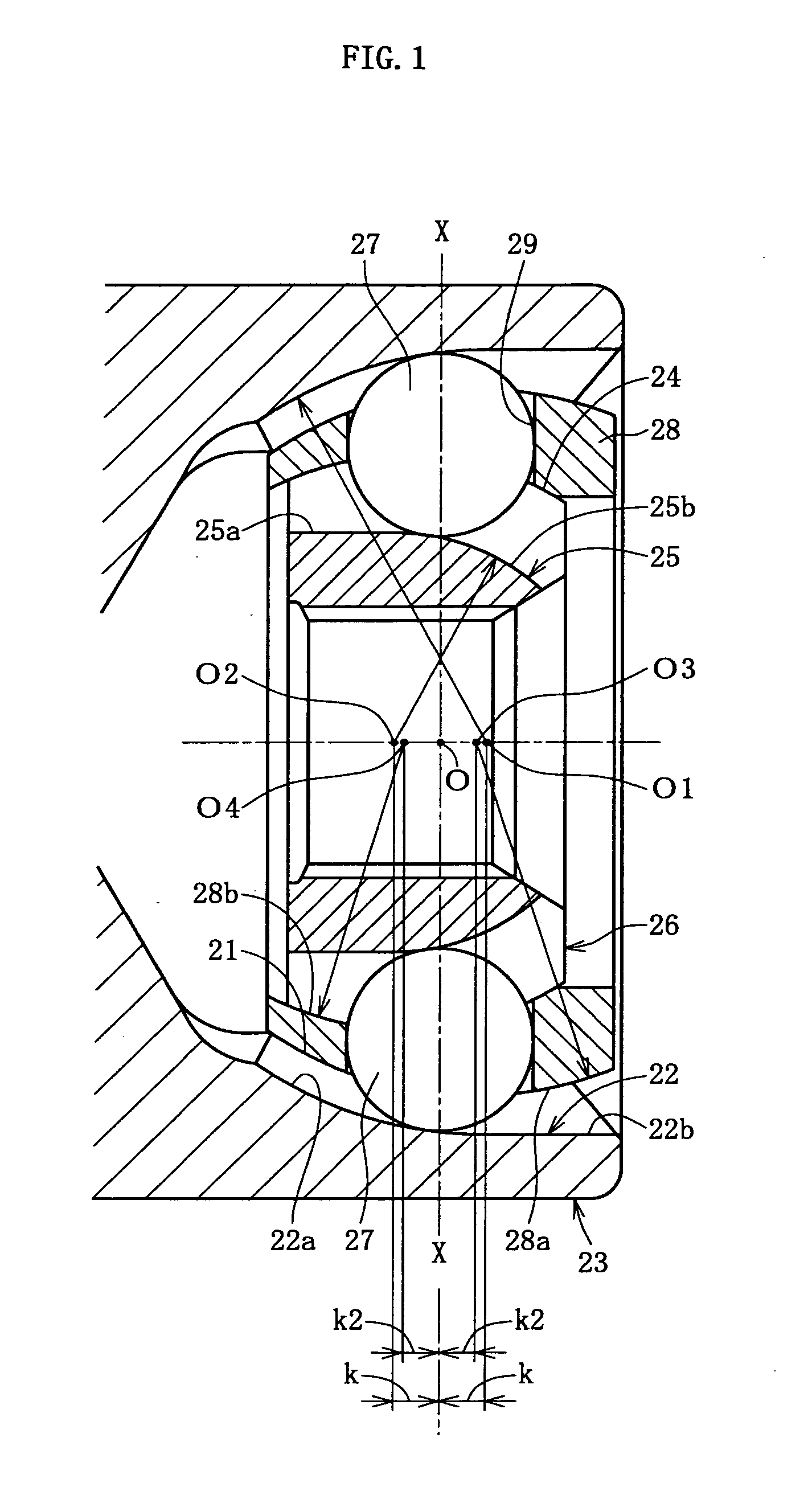
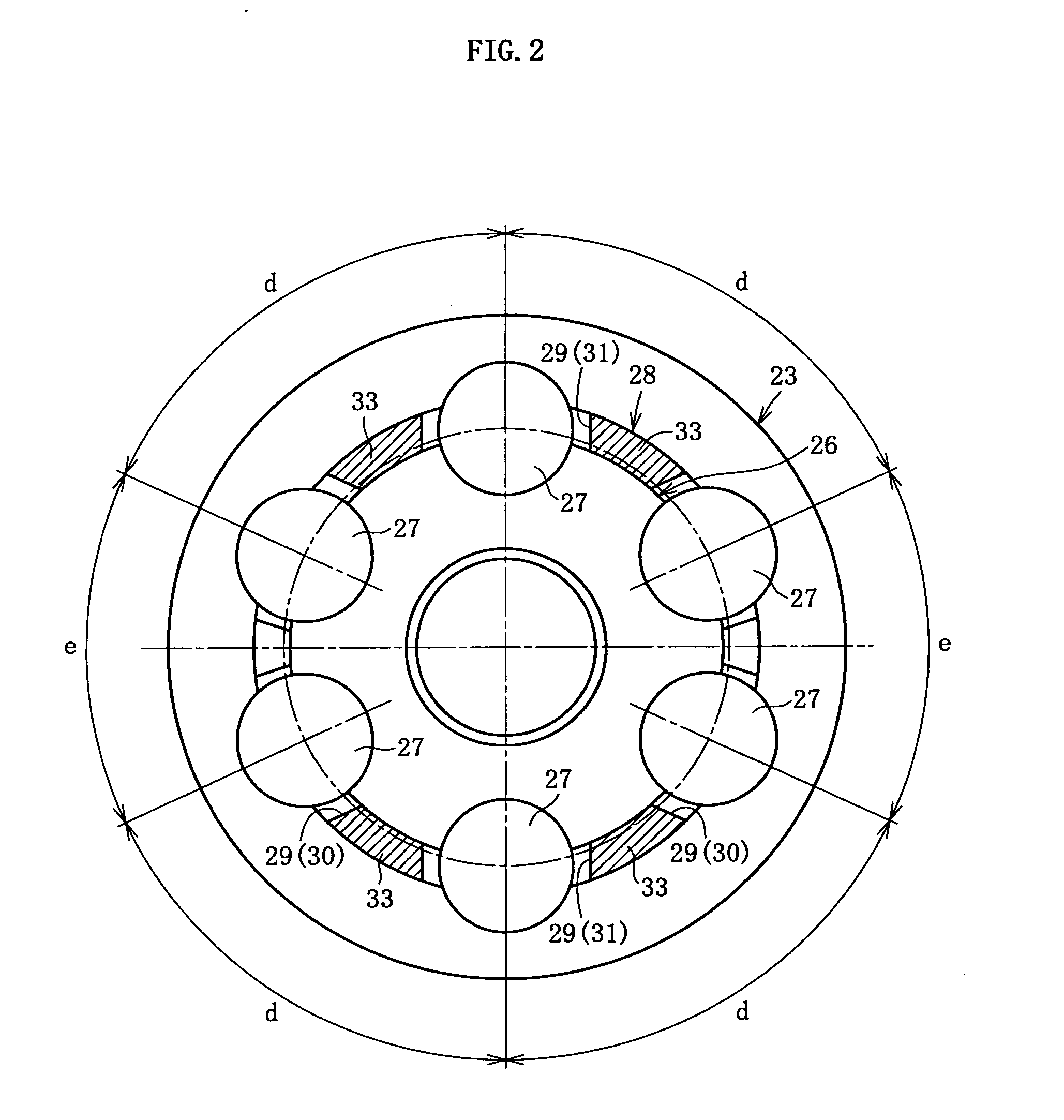
[0084]As shown in FIG. 1, a fixed constant velocity universal joint according to the basic embodiment includes an outer ring 23, an inner ring 26, a plurality of balls 27, and a cage 28. The outer ring 23 serves as an outer member in which a plurality of track grooves 22 are formed on an inner spherical surface 21 along an axial direction, unevenly spaced in a circumferential direction. The inner ring 26 serves as an inner member in which a plurality of track grooves 25 paired with the track grooves 22 on the outer ring 23 are formed on an outer spherical surface 24 along an axial direction, unevenly spaced in a circumferential direction. The balls 27 are interposed between the track grooves 22 of the outer ring 23 and the track groove...


PUM


Abstract

The present invention provides a fixed constant velocity universal joint that can be made compact, has little decrease in load capacity even when the fixed constant velocity universal joint is made compact and is at an operating angle, and can improve high angle strength and durability through lessening instances in which a ball runs over a track at a high angle. In the fixed constant velocity universal joint of the present invention, a cage 28 includes four pockets 29, the pockets 29 being a pair of long pockets 30 of which a circumferential direction spacing is wide and a pair of short pockets 31 of which the circumferential direction spacing is narrow. The pair of long pockets 30 are shifted by 180 degrees along a circumferential direction and a pair of short pockets 31 are shifted by 180 degrees along the circumferential direction. As a result, the long pockets 30 and the short pockets 31 are alternately disposed along the circumferential direction. A long pocket 30 houses two balls 27. A short pocket 31 houses one ball. Two ball housing sections 38 connected by a slit 37 are formed in the long pocket 30 by projections 36 that project towards a long pocket inner side being provided on opposing long sides 35 of the long pocket 30.

Description

TECHNICAL FIELD[0001]The present invention relates to a fixed constant velocity universal joint used in a power transmission system of automobiles and various industrial machineries. The fixed constant velocity universal joint allows angular displacement between two axes on a driving side and a driven side.BACKGROUND ART[0002]A fixed constant velocity universal joint is a kind of constant velocity universal joint that is, for example, used as a means for transmitting rotational force from an engine to wheels of an automobile at a constant speed. The fixed constant velocity universal joint has a configuration in which two axes on a driving side and a driven side are connected, and rotational torque can be transmitted at a constant speed even when the two axes are at an operating angle. In general, a Birfield-type (BJ) and an undercut-free type (UJ) are widely known as the fixed constant velocity universal joint described above.[0003]For example, the UJ-type fixed constant velocity un...

Claims


Application Information

Patent Timeline
IPC IPC(8): F16D3/224F16D3/223F16D3/2237
CPCF16D3/223F16D2300/12F16D2003/22303F16D3/2237Y10S464/906
Inventor FUJIO, TERUAKIHOSHINO, MANABUNAKAGAWA, TOHRUSUGANUMA, WASABURO
Owner NTN CORP
Why Eureka
Try Eureka