

Rolling bearing
- Summary
- Abstract
- Description
- Claims
- Application Information
AI Technical Summary
Benefits of technology
Problems solved by technology
Method used
Image

Examples
first embodiment
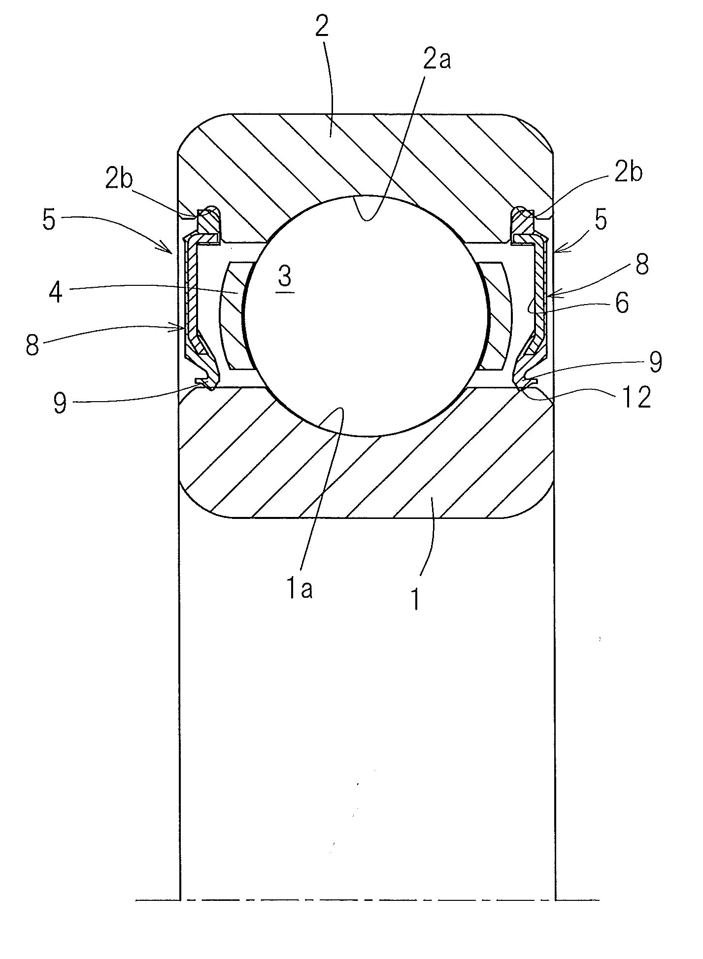
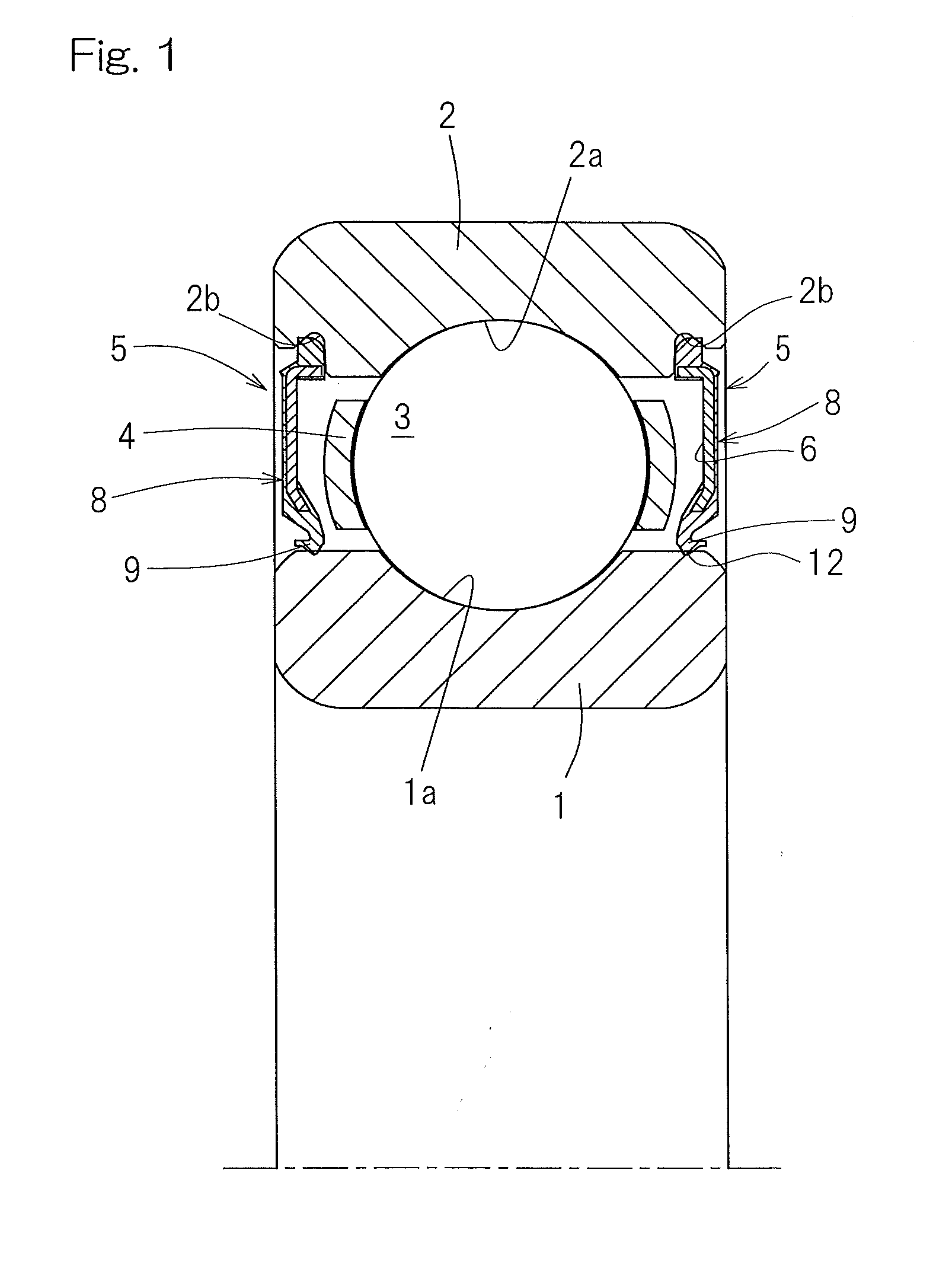
[0039]the present invention will be described in detail with particular reference to FIGS. 1 to 6. A rolling bearing assembly according to this embodiment is used in, for example, a transmission for automotive vehicles. As shown in FIG. 1, the rolling bearing assembly includes a plurality of rolling elements 3 interposed between a raceway 1a of an inner ring and a raceway 1b of an outer ring, which are raceway rings. The inner and outer rings 1 and 2 and the rolling elements 3 are made of a high carbon chrome bearing steel, such as, for example, SUJ 2 or the like, or martensite based stainless steel or the like. It is to be noted that the present invention is not limited to the use of such specific steel material. The rolling elements 3 are provided in a retainer 4 for retaining them and an annular bearing space delimited between the inner and outer rings 1 and 2 have its opposite ends sealed by respective seal members 5. A grease is initially filled within the bearing assembly. Thi...
second embodiment
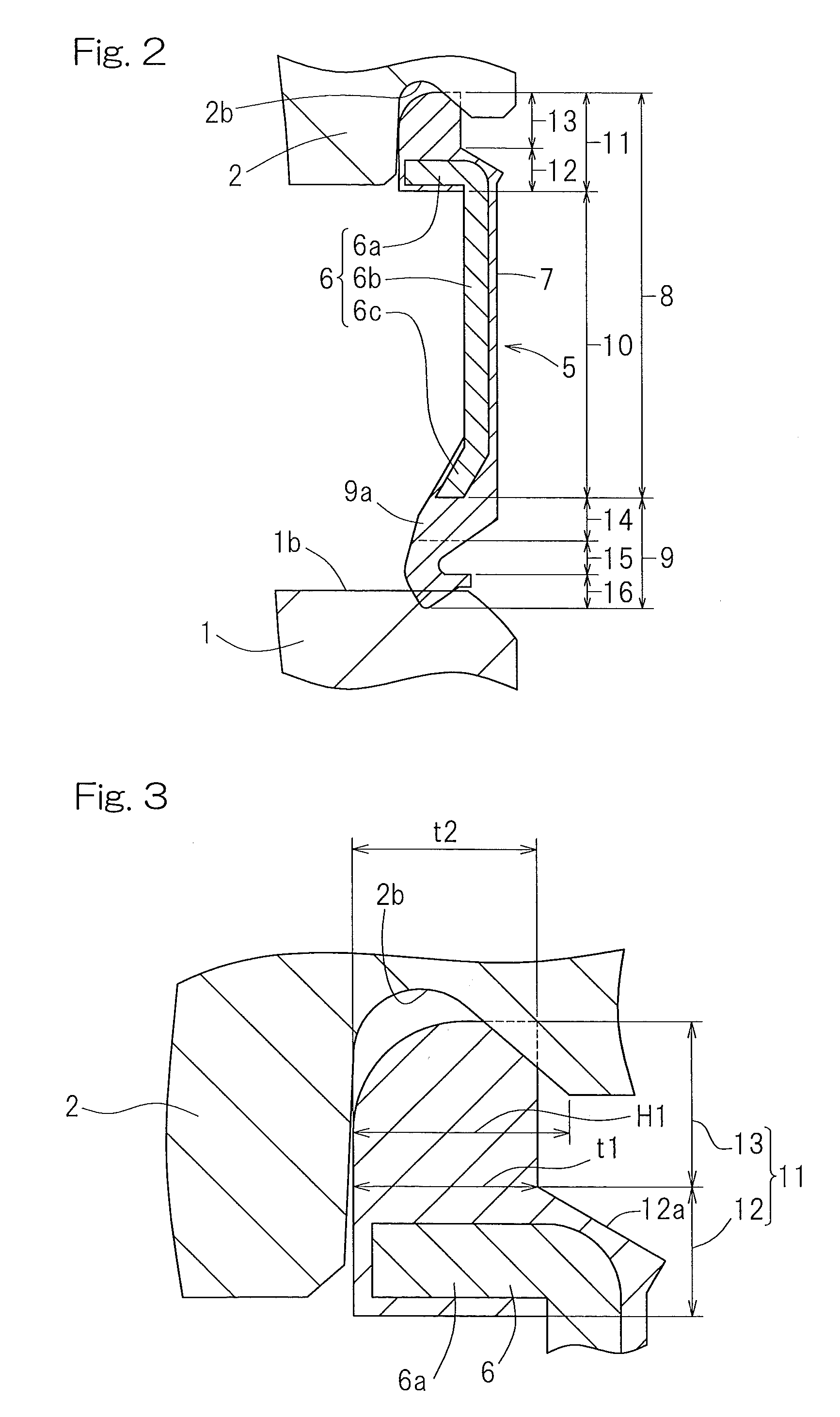
[0053]As shown in FIG. 7 in connection with the second embodiment, the drag-rotation preventive fitting structure may be accomplished when the outer diametric dimension D1 of the fitting section 13 of the seal member main body 8 is chosen to be equal to or greater than 95% and less than 100% of the diametric diameter D2 of the groove bottom in the seal mounting groove 2b. More specifically, the outer diametric dimension D1 of the fitting section 13 is so formed as to have a value that is larger by a predetermined length (for example, 0.3 mm) than the outer diametric dimension of the fitting section of the seal member main body employed in the conventional rolling bearing assembly of the same size. Even in this case, the constraining force of the seal member 5 can be enhanced. Such being the case, even though the sealing lip torque is high, the fitting section 13 of the seal member main body 8 maintains the condition in which it is fitted into the seal mounting groove 2b in the outer...
third embodiment
[0054]As shown in FIG. 8 in connection with a third embodiment, the core metal 6 may include a thick-walled section embedded segment 6aa, which is embedded in the thick-walled section 12, and a fitting section-embedded segment 6ab integral with this thick-walled section embedded segment 6aa and embedded in the fitting section 13. Also, each of the thick-walled section embedded segment 6aa and the fitting section-embedded segment 6ab has a sectional shape inclined inwardly of the bearing assembly as it goes towards a tip end. As compared with each of the previously described embodiments, since the core metal 6 includes the fitting section-embedded segment 6ab embedded in the fitting section 13, the rigidity of the base end portion 11 of the seal member main body 8 can be further increased. In addition, thanks to the thick-walled section embedded segment 6aa and the fitting section-embedded segment 6ab having the inclined sectional shape as described above, the rigidity of the base en...
PUM
 Abstract
Description
Claims
Application Information