Door panel

US20100031604A1Inactive Publication Date: 2010-02-11KEJTERPILLAR R L
7 Cites 4 Cited by

Patent Information

Authority / Receiving Office
US · United States
Current Assignee / Owner
Publication Date
2010-02-11
Estimated Expiration
Not applicable · inactive patent

Smart Images

  • Figure 1
    Figure 1
  • Figure 2
    Figure 2
  • Figure 3
    Figure 3
Patent Text Reader

Abstract

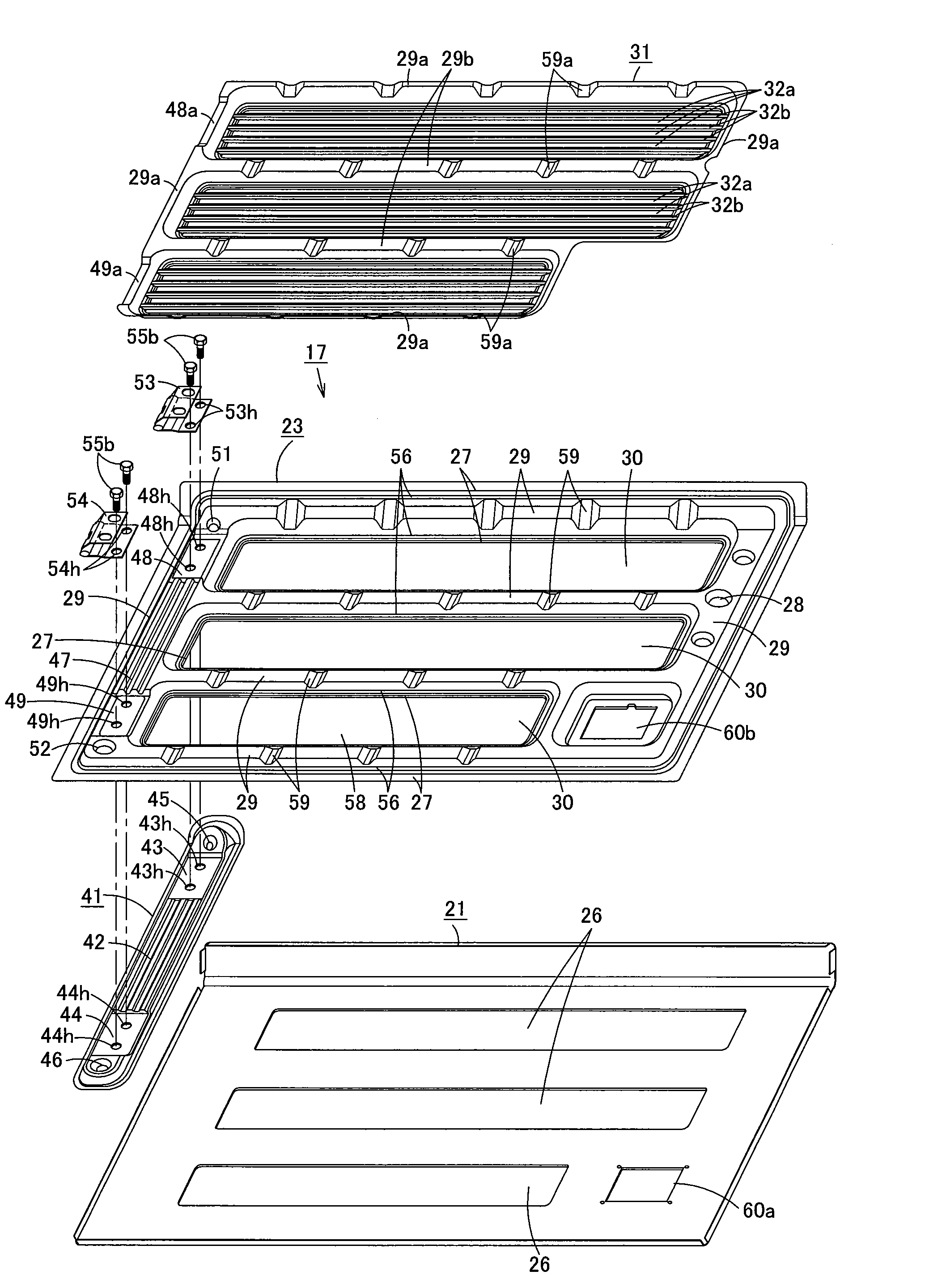
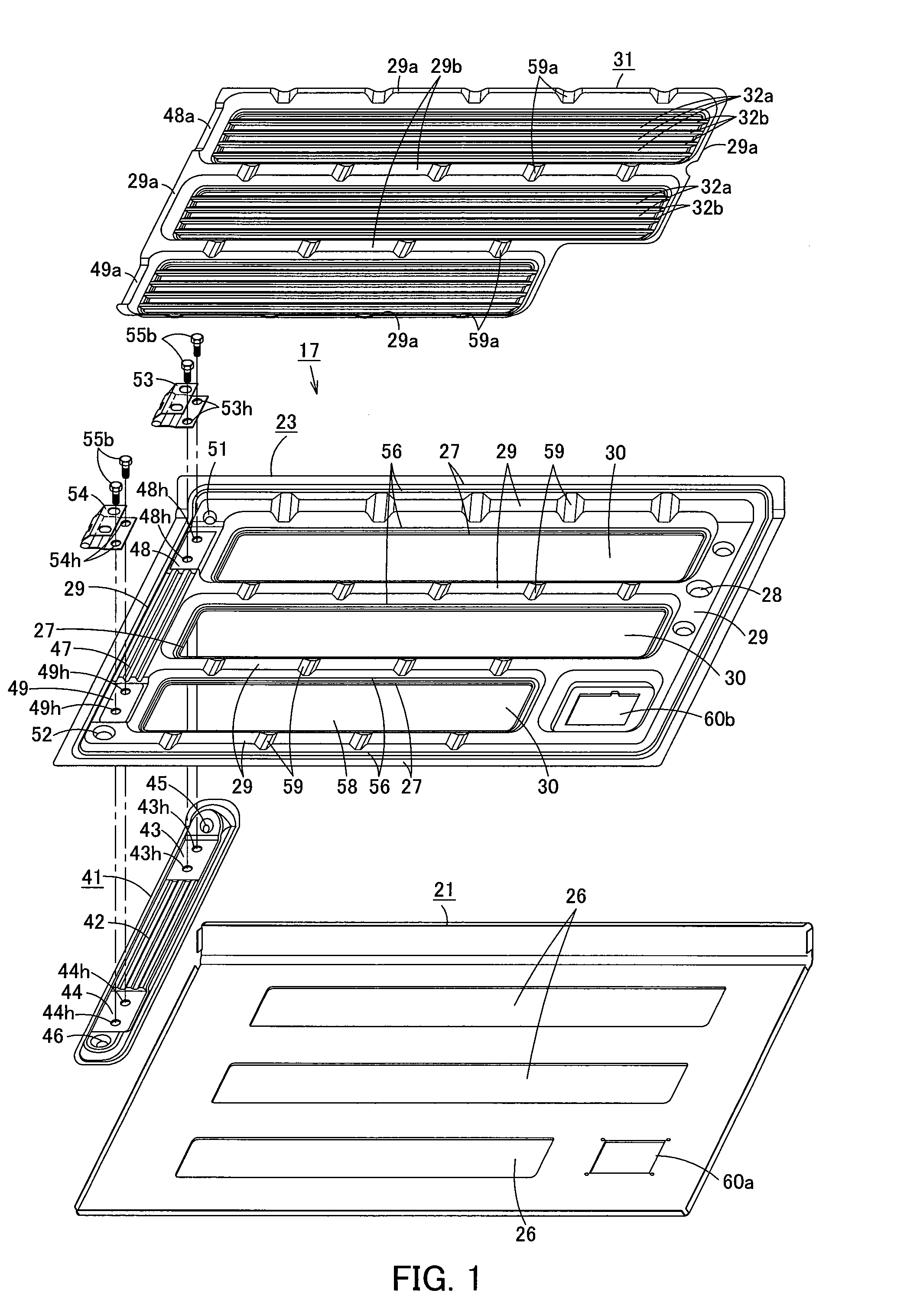
A door panel that permits formation of small ventilation holes therein while ensuring adequate rigidity is provided. The door panel includes an outer panel, an inner panel, and a perforated ridge-and-furrow plate. The outer panel has openings, and the inner panel has openings. The inner panel is formed by means of press molding so as to have an uneven surface with recessed portions and a raised portion, with the raised portion protruding away from the outer panel and the recessed portions recessed towards and fixed to the inner surface of the outer panel. The perforated ridge-and-furrow plate is attached to the reverse side of the inner panel. The perforated ridge-and-furrow plate is a punching plate that is already provided with numerous small, circular ventilation holes, or with ventilation holes arranged in a mesh or a honeycomb shape. The perforated ridge-and-furrow plate includes alternating furrow portions and ridge portions formed in the region that corresponds to the openings of the inner panel.
Need to check novelty before this filing date? Find Prior Art

Description

CROSS-REFERENCE TO PRIOR APPLICATION

[0001] This is a U.S. national phase application under 35 U.S.C. §371 of International Patent Application No. PCT / JP2008 / 062167 and claims the benefit of Japanese Application No. 2007-316860, filed Dec. 7, 2007. The contents of the above applications are incorporated herein in their entirety. The International Application was published in Japanese on Jun. 11, 2009 as WO2009 / 072317 A1 under PCT Article 21(2).TECHNICAL FIELD

[0002] The present invention relates to a door panel that is provided with an outer panel and an inner panel.BACKGROUND OF THE INVENTION

[0003] FIG. 9 illustrates a hydraulic excavator 10, which is a work machine. The hydraulic excavator 10 includes a lower structure 11, an upper structure 12, a cab 13, a work equipment 14, and a power system 15 that includes an engine. The cab 13, the work equipment 14, and the power system 15 are mounted on the upper structure 12, which is rotatably mounted on the lower structure 11. The power syst...

Examples

Embodiment Construction

[0027]Next, the present invention is explained hereunder, referring to an embodiment thereof shown in FIGS. 1 to 8.

[0028]FIG. 8 illustrates a hydraulic excavator 10, which is a work machine. The hydraulic excavator 10 includes a lower structure 11, an upper structure 12, a cab 13, a work equipment 14, and a power system 15 that includes an engine. The cab 13, the work equipment 14, and the power system 15 are mounted on the upper structure 12, which is rotatably mounted on the lower structure 11. The power system 15 is covered by a top cover 16, side doors 17, and other such components. Each side door 17 is mounted by hinges so as to be capable of opening and closing, and maintained in the closed state by means of a latching device 18, which will be explained later.

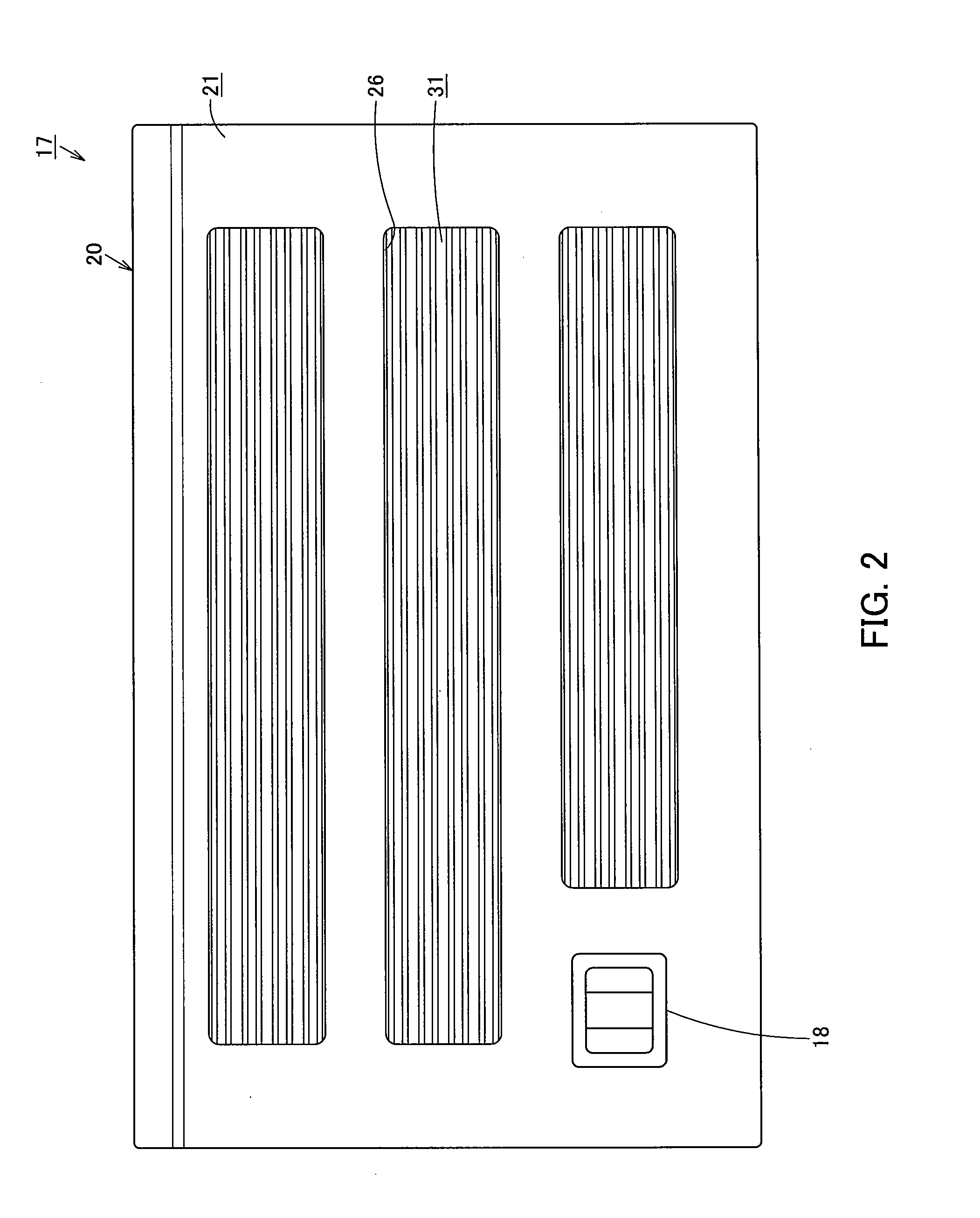
[0029]FIGS. 1 to 7 illustrate a door panel 20 of a side door 17. As illustrated in FIG. 4, the door panel 20 includes an outer panel 21, an inner panel 23, and a foamed material 24. The inner panel 23 is formed by means o...