Co-centric pin spanner tool

Active Publication Date: 2019-04-25
MOTION PRO
View PDF12 Cites 0 Cited by
  • Summary
  • Abstract
  • Description
  • Claims
  • Application Information

AI Technical Summary

Benefits of technology

[0020]An advantage of the present invention is that it makes it easier to provide. transmitted torque which is equal to the torque applied to the tool pivot.
[0021]Another advantage is that torque is applied to the tool pivot.
[0022]A further advantage of the present invention is that the tool can easily apply torque which is not magnified, so no re-calculation of torque is necessary.
[0023]Another advantage of th

Problems solved by technology

The problem may be compounded when the component is located in an inaccessible area where direct access to the pin indents is not possible.
This extended reach presents the difficulty that the tool may need to remain level while applying torque to the component, so that the pins stay engaged with the pin indents and are not tilted out of the indents.
This means that if a specific torque is required to be applied by the torque wrench 11, the magnifier must be calculated and the applied torque by the wrench 11 must be accordingly reduced, which is inconvenie

Method used


Image

  • Co-centric pin spanner tool
  • Co-centric pin spanner tool
  • Co-centric pin spanner tool

Examples


Embodiment Construction

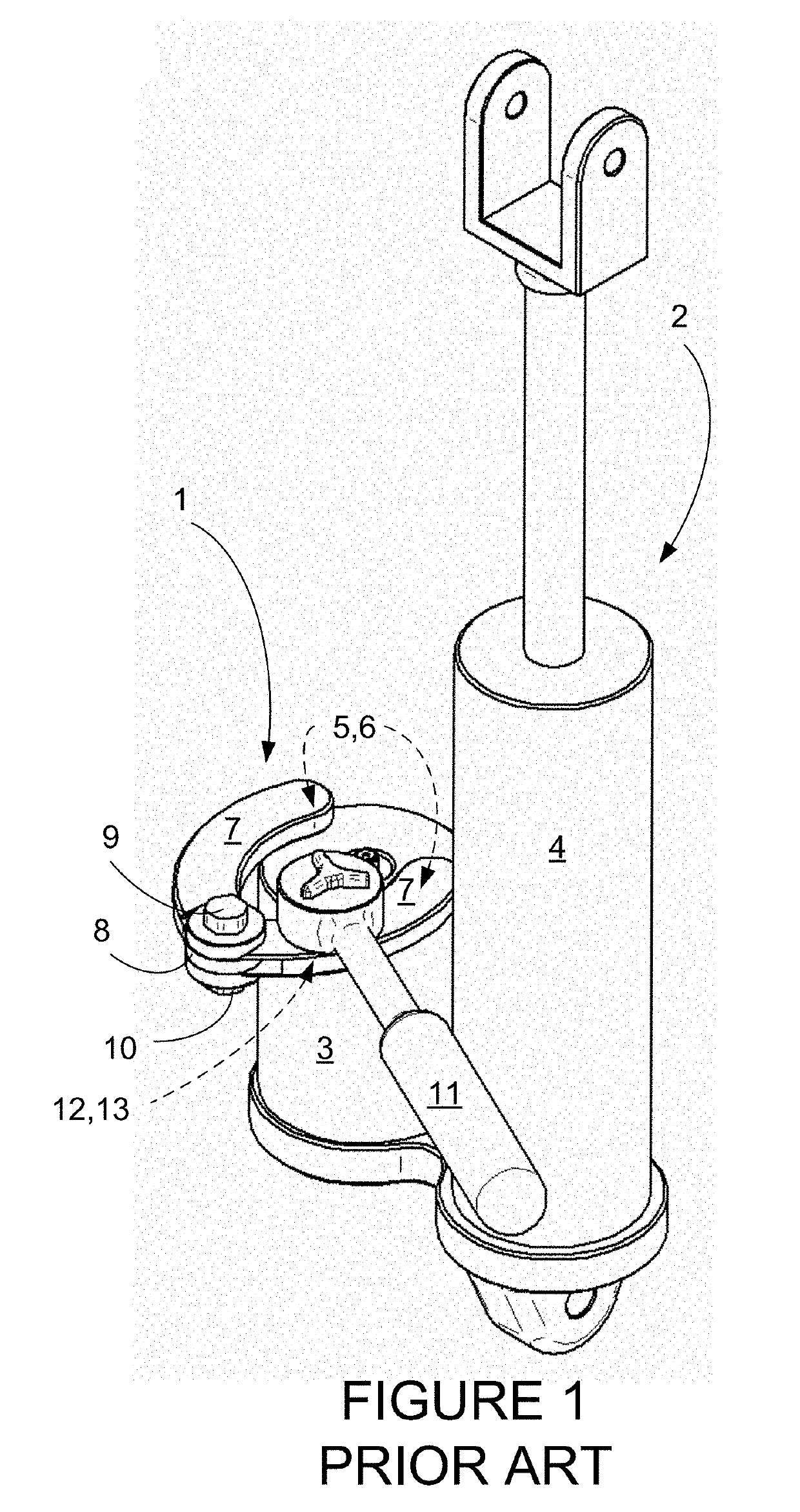
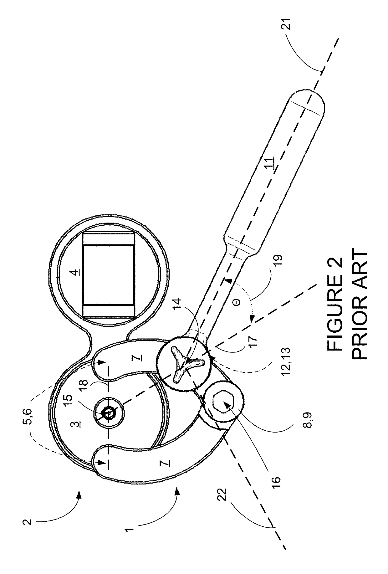
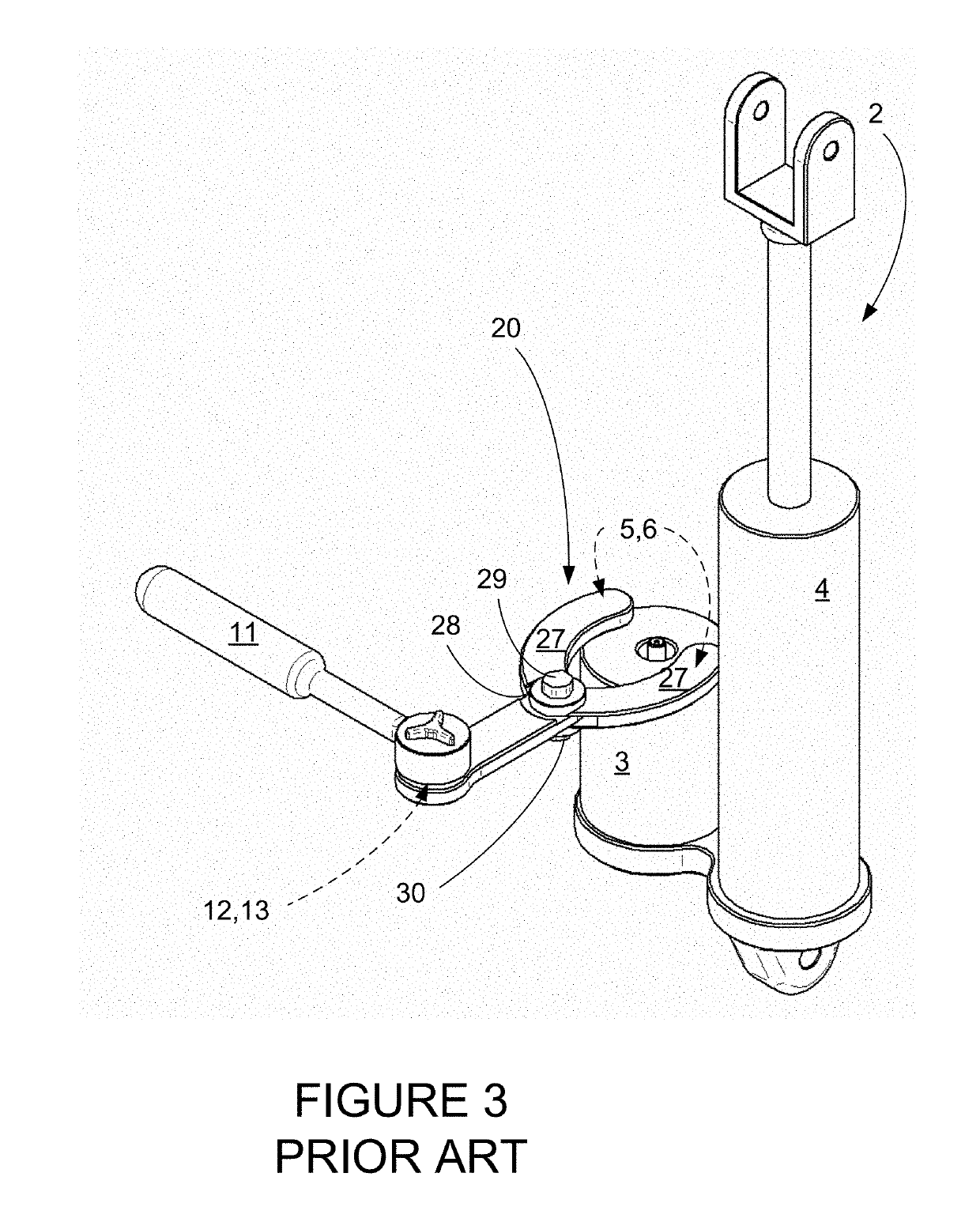
[0034]The present invention is a pin spanner with drive and pivot which are co-centric, meaning that the center of axis of rotation of the drive aligns with the center of axis of rotation of the pivot of the arms. This will be referred to as a co-centric pin spanner and designated as co-centric pin spanner 41. When elements are unchanged from the previous tools discussed above, the numbering will remain the same. When an element is similar to a previous element, but with unique variations of the present invention, an effort will be made to use the same part number, but prefaced by the number “4”, so that the previous arms 7, will be numbered arms 47, and so on.

[0035]The co-centric pin spanner 41 is illustrated in FIGS. 5-8. In FIGS. 5-6, the co-centric pin spanner 41 is shown engaged with a torque wrench 11 and a shock absorber 2 having a reservoir 3 with indents 5. Referring now also to FIGS. 7-8, the co-centric pin spanner 41 includes two arms 47, one of which is a driven arm 48, ...


PUM


Abstract

A pin spanner tool for use with a driver having a center of rotation, the pin spanner having a driven arm, a floating arm, and a bolt connecting the driven arm and the floating arm, where the bolt has a center of rotation which is co-centric with the center of rotation of the driver.

Description

TECHNICAL FIELD[0001]The present invention relates generally to tools for applying measured torque to mechanical components.BACKGROUND ART[0002]There are a number of applications in which a specialized tool called a pin spanner is necessary to install or remove various engine or mechanical components. These components are configured with indents or holes which are engaged by pins on the pin spanner tool, and torque applied to the tool which is then transmitted to the component to rotate it, typically to screw or unscrew the component from a fixture. Often, the amount of torque applied is important to make sure that the component is not over-tightened or under-tightened, so a torque-wrench may be used.[0003]The problem may be compounded when the component is located in an inaccessible area where direct access to the pin indents is not possible. In this case, the tightening tool may need to reach laterally under overhanging items in order to engage the pins into the pin indents. This ...

Claims


Application Information

Patent Timeline
IPC IPC(8): B25B13/48B25B23/00
CPCB25B13/481B25B23/0007B25B13/30B25B13/48B25B13/28
Inventor WILSON, JEFFREY NICHOLASSCOTT, STEVEN RICHARD
Owner MOTION PRO
Why Eureka
Try Eureka