Label with bendable part

Active Publication Date: 2009-11-26
SCHREINER GRP GMBH & CO KG
View PDF9 Cites 5 Cited by
  • Summary
  • Abstract
  • Description
  • Claims
  • Application Information

AI Technical Summary

Benefits of technology

[0009]The reinforcement area can also be produced by a local increase in the rigidity. Weakenings or perforations can be provided along one or more curves in the section that can be bent. The local increase in rig

Problems solved by technology

A disadvantage of the solution known from DE 10017142 is that add

Method used


Image

  • Label with bendable part
  • Label with bendable part
  • Label with bendable part

Examples


Embodiment Construction

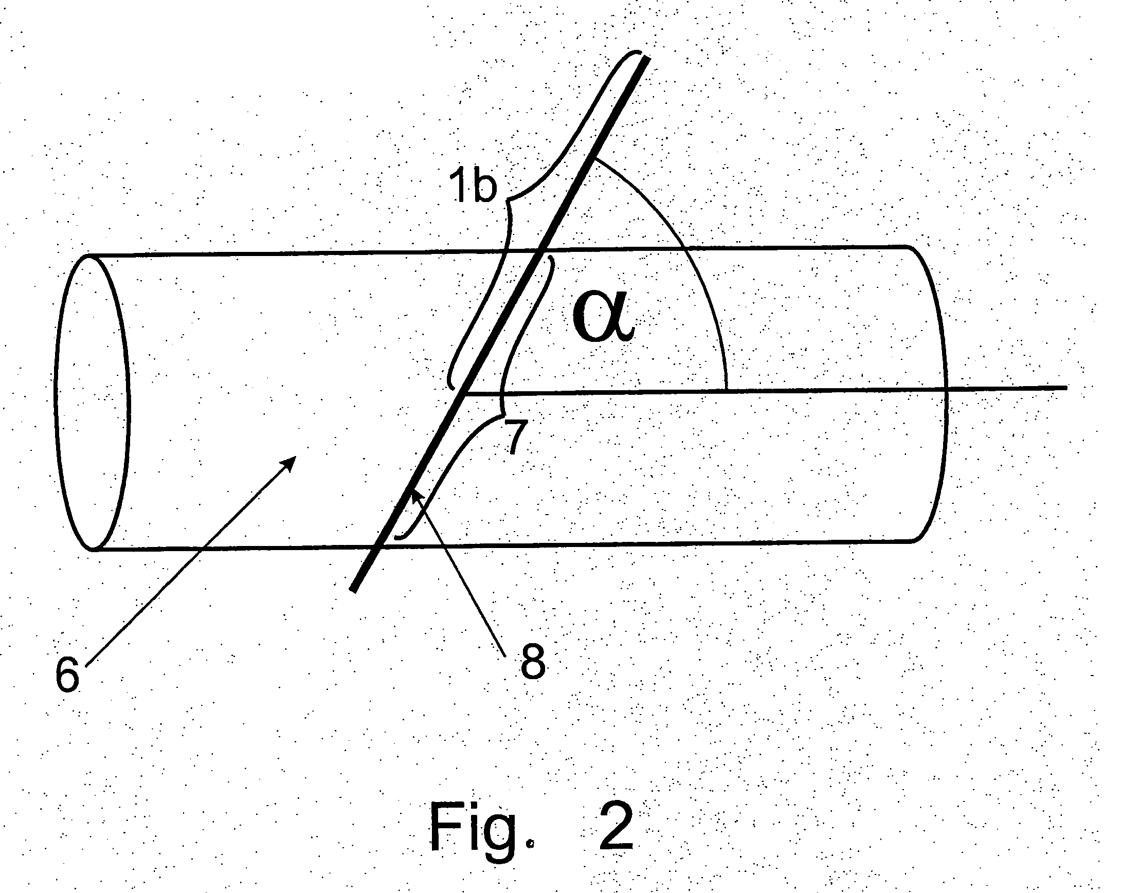
[0018]The term “curved surfaces” is intended below to mean all surfaces that have a curvature in the area of the raising-up axis of the label, but especially surfaces of extrusion bodies with a round or elliptical cross-section and here, in particular, cylinders (tubes). The term label is understood to mean all film-like information carriers that can be bonded to the object to be labeled. In addition to adhesion (self-adhesive labels), all other common bonding techniques, such as permanent cementing, welding, stapling, riveting, etc., can also be taken into consideration.

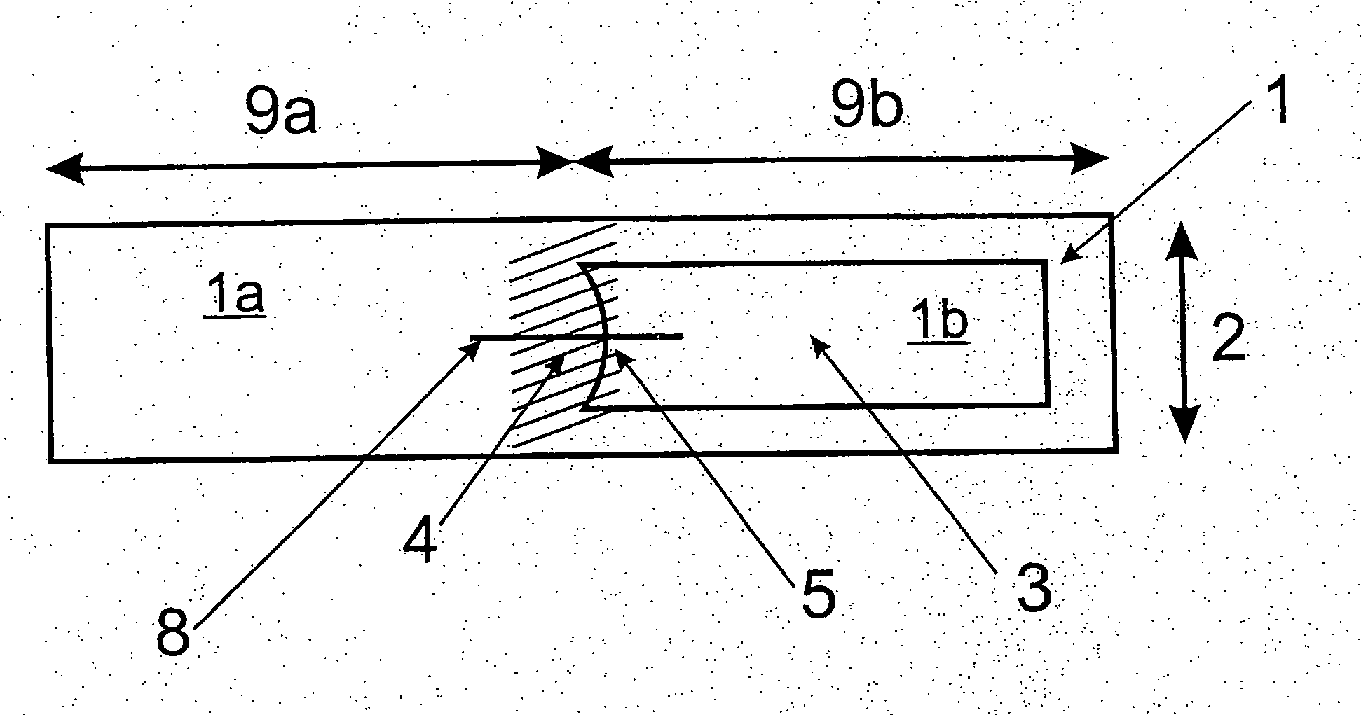
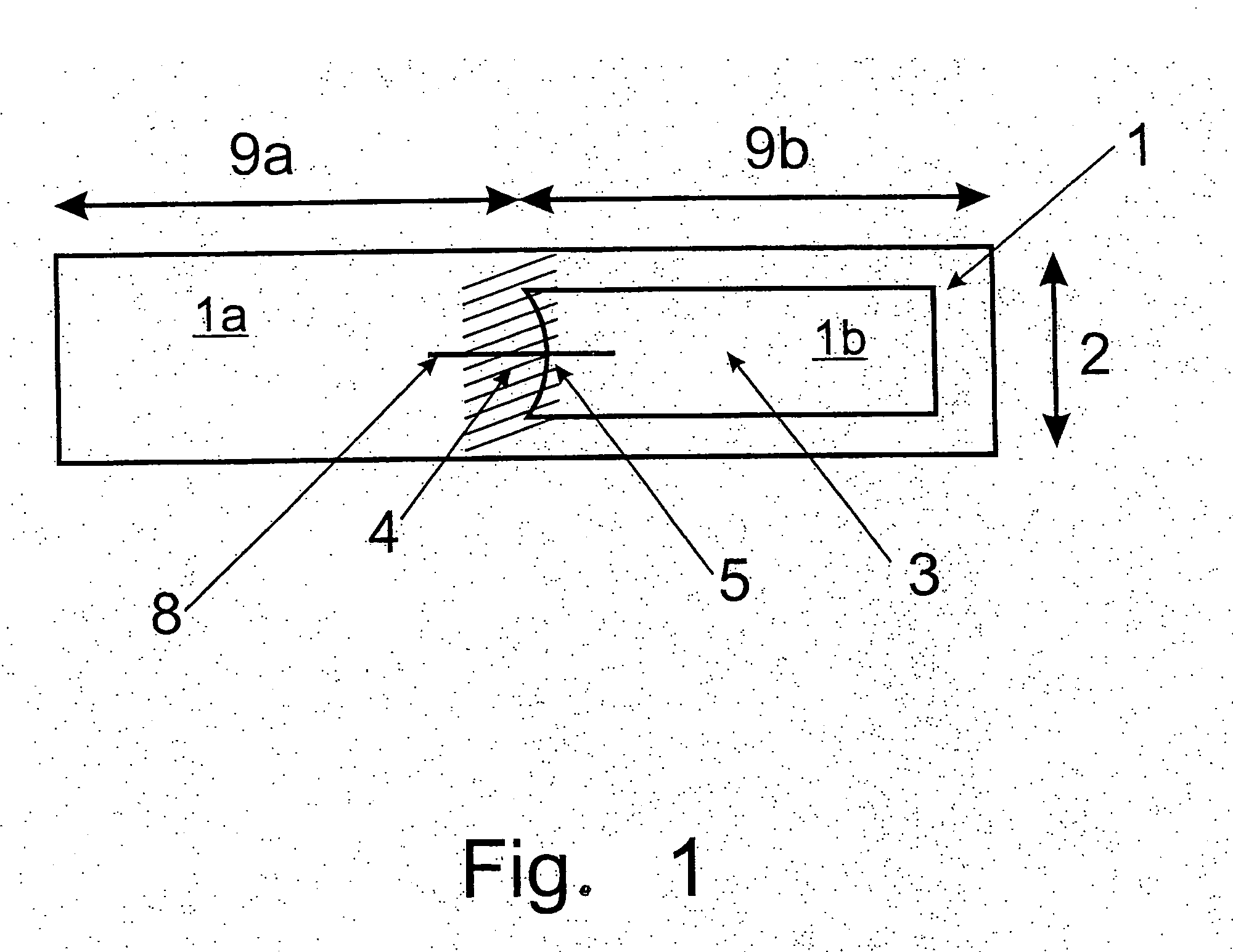
[0019]FIG. 1 shows the fundamental structure of a label 1 in accordance with the invention. The label 1, to be affixed later on the surfaces curved in direction 2 (transverse to extension 9a, 9b), consists of two partial areas 1a and 1b, which are defined by a crease area 4 and the left end of a reinforcement area 3. The crease area 4 can be formed by a weakening of the label material 1 (scoring, perforation, or the...


PUM


Abstract

A label has a part that is to stand out at a defined angle from a curved surface to which the label is applied. There is a reinforcement area that has an edge curvature at the transition part of the label, between the part that is to be raised up and the part that is attached to the curved surface. The edge curvature is implemented such that it fixes the part to be raised up at a defined angle during or after placement of the label on a specific object.

Description

CROSS-REFERENCE TO RELATED APPLICATIONS[0001]Applicants claim priority under 35 U.S.C. §119 of German Application No. 10 2006 049 042.8, filed Oct. 18, 2006. Applicants also claim priority under 35 U.S.C. §365 of PCT Application No. PCT / EP2007 / 060205 filed Sep. 26, 2007. The international application under PCT article 21(2) was not published in English.BACKGROUND OF THE INVENTION[0002]The invention concerns a label with a structure that enables sticking it to curved structures, and to subsequently place a part of the label at a defined angle from the curved surface.[0003]Such a label part, sticking out from a surface at a defined angle, can be useful for various tasks. With a label stuck on a tube, for example, this label part can contain information concerning the medium conveyed in the tube or the technical state of the tube. Readability is facilitated, in this case, with the information part sticking out away from the tube. Another area of application for a label part protruding,...

Claims


Application Information

Patent Timeline
IPC IPC(8): B32B1/08B32B3/10B32B1/00
CPCG09F3/0295G09F3/10G09F2003/0272Y10T428/13Y10T428/24628G06K19/0776Y10T428/24273G09F2003/0273Y10T428/1334Y10T428/1345Y10T428/1352
Inventor MOOSHEIMER, ULRICHMAIR, JOSEF
Owner SCHREINER GRP GMBH & CO KG
Why Eureka
Try Eureka