Wire harness fixing structure

a technology of fixing structure and wire harness, which is applied in the direction of electrical/fluid circuit, electrical apparatus, vehicle components, etc., can solve the problems of not being suitable in some cases, and achieve the effect of increasing the contact area between the wire harness and the interior member, simple fixing, and simple fixing

Inactive Publication Date: 2020-02-27
AUTONETWORKS TECH LTD +2
View PDF5 Cites 8 Cited by
  • Summary
  • Abstract
  • Description
  • Claims
  • Application Information

AI Technical Summary

Benefits of technology

[0017]According to the first to seventh aspects, a contact area between the wire harness and the interior member can be increased, thus even when a force for the fixation per unit area is small, the wire harness can be fixed to the interior member. Thus, the wire harness can be fixed to the interior member also by previously providing a fixing member on the wire harness. Accordingly, the wire harness can be simply fixed, in assembling the vehicle, even to a mounting object which is not suitable for having a clamp hole to fix a clamp.
[0018]Particularly, according to the second aspect, the wire harness can be simply fixed by using the pressure sensitive adhesive double sided tape.
[0019]Particularly, according to the third aspect, the wire harness can be simply fixed by using the touch fastener.
[0020]Particularly, according to the fourth aspect, the wire harness can be fixed to the plate-like member by using the male member provided on the wire harness. At this time, the surface layer in the plate-like member is formed of the material having the characteristics that the hooks can be hooked, thus the male member can be fastened on any position in the plate-like member.
[0021]Particularly, according to the fifth aspect, the wire harness can be simply fixed by using the plate-like member and the attaching member.
[0022]Particularly, according to the sixth aspect, it can be suppressed that the electrical wire is sandwiched with the large force.

Problems solved by technology

However, when the mounting object of the wire harness is a member exposed indoors such as the roof lining described in Patent Document 2, there is a possibility that the clamp may be exposed indoors in a case where a hole for fixing the clamp is formed in the member and the clamp is inserted into and locked to the hole.
As described above, it may not be appropriate in some cases, depending on the mounting object, to apply the technique of forming the hole for fixing the clamp and fixing the clamp.

Method used


Image

  • Wire harness fixing structure
  • Wire harness fixing structure
  • Wire harness fixing structure

Examples


embodiment

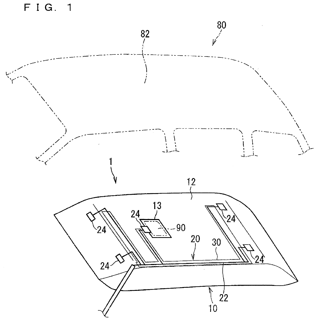
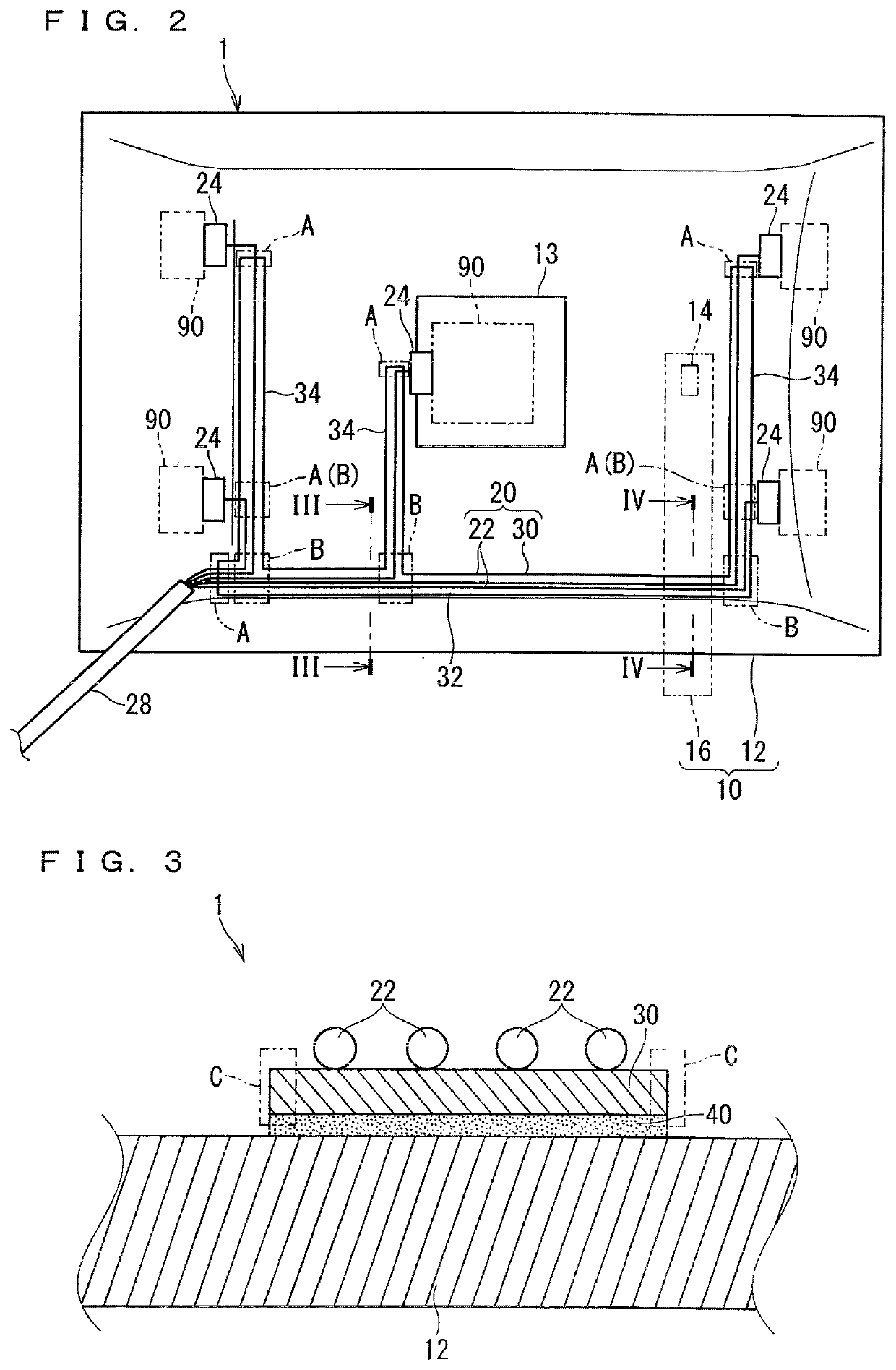
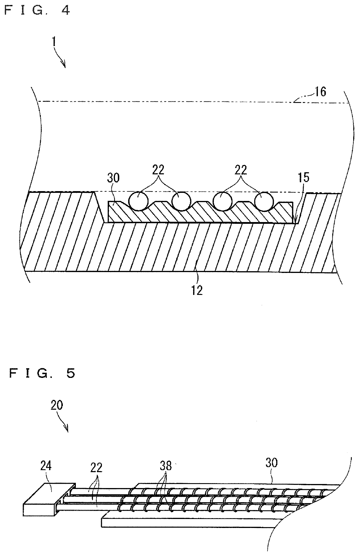
[0034]A wire harness fixing structure according to an embodiment is described hereinafter. FIG. 1 is a schematic exploded perspective view illustrating a wire harness fixing structure 1 according to the embodiment and an assembling object thereof. FIG. 2 is a schematic plan view illustrating the wire harness fixing structure 1 according to the embodiment. FIG. 3 is a cross-sectional view of the wire harness fixing structure 1 cut along a III-III line in FIG. 2. FIG. 4 is a cross-sectional view of the wire harness fixing structure 1 cut along a IV-IV line in FIG. 2.

[0035]The wire harness fixing structure 1 according to the embodiment includes an interior member 10 and a wire harness 20 fixed to the interior member 10.

[0036]The interior member 10 is a member interiorly mounted on a vehicle. Specifically, the interior member 10 includes a plate-like member 12. Herein, the interior member 10 further includes an attaching member 16 incorporated into the plate-like member 12.

[0037]More sp...

modification example

[0076]In the example illustrated in FIG. 2, a flow path of the duct is set to cross the electrical wires 22, however, this configuration is not necessary. There may be a case where the flow path of the duct is parallel to the electrical wires 22. In this case, the duct preferably crosses the electrical wires 22 in a width direction (a direction orthogonal to an extension direction of the flow path). At this time, a width dimension of the duct is preferably set larger than a distance between the two electrical wires 22 located outermost in the plurality of flatly formed electrical wires 22. Accordingly, all of the electrical wires 22 parallel to the duct can be sandwiched between the duct and the plate-like member 12.

[0077]Each configuration described in the embodiment and each modification example can be appropriately combined as long as they are not contradictory. For example, when one wire harness 20 is fixed to the interior member 10, applicable are the three fixing structures de...


PUM


Abstract

A wire harness fixing structure includes an interior member including a plate-like member and interiorly mounted on a vehicle and a wire harness including an electrical wire disposed along the plate-like member and a sheet material to which the electrical wire is fixed by sewing or welding. The wire harness is fixed to the interior member while the sheet material is spread.

Description

TECHNICAL FIELD[0001]The present invention relates to a technique of fixing a wire harness to a mounting object.BACKGROUND ART[0002]A technique of fixing a wire harness to a mounting object is described in Patent Documents 1 and 2, for example. Patent Document 1 discloses a technique of fixing a wire harness to a mounting object using a clamp (also referred to as a clip, for example). Patent Document 2 discloses a technique of fixing a roof harness to a roof lining (also referred to as a head lining or a roof trim, for example).[0003]Herein, when the wire harness is fixed using the clamp as is the case for Patent Document 1, a hole for fixing the clamp needs to be formed in the mounting object. However, when the mounting object of the wire harness is a member exposed indoors such as the roof lining described in Patent Document 2, there is a possibility that the clamp may be exposed indoors in a case where a hole for fixing the clamp is formed in the member and the clamp is inserted ...

Claims


Application Information

Patent Timeline
Patent Type & Authority Applications(United States)
IPC IPC(8): B60R16/02H02G3/32H02G3/00H02G3/34
CPCH02G3/34B60R16/0215H02G3/266H02G3/32H02G3/30H02G3/305
Inventor MIZUSHITA, MASAKIITO, KENTANAKAMURA, YUICHIHIEI, SUSUMUYAMAGUCHI, KOHEIFUKAI, DAISUKENAKANO, HARUKAYOKOI, MOTOHIROMIZUNO, HOUSEI
Owner AUTONETWORKS TECH LTD
Why Eureka
Try Eureka