Lacing cord and shoes using the same

a technology of laced cords and shoes, applied in the direction of fastenings, travelling articles, travelling sacks, etc., can solve the problems of substantial force and necessary rotational force, and achieve the effect of reducing the force for tightening the shoe body, loosening the tightness of the shoe, and easy removal of the sho

Active Publication Date: 2014-07-17
SHIMANO INC
View PDF3 Cites 13 Cited by
  • Summary
  • Abstract
  • Description
  • Claims
  • Application Information

AI Technical Summary

Benefits of technology

[0018]In this shoe, the shoe body is tightened by winding the lacing cord, which has protruding parts protruding in the direction that intersects with the axial direction, according to a winding member. Here, a lacing cord wherein the protruding parts were provided and the contact area to the guide parts was minimized is used. Therefore, the force for tightening the shoe body can be reduced.
[0019]In accordance with a tenth aspect of the present invention, the lacing cord according to the ninth aspect is configured so that the winding member has a release mechanism that loosens the tightness of the shoe. In this case, the tightness of the lacing cord can be loosened when removing the shoe. Therefore, the shoe can be removed easily.
[0020]According to the lacing cord disclosed in the present disclosure, the contact area between the guide parts and the lacing cord is minimized, and the force necessary for tightening the article to be laced can be reduced.

Problems solved by technology

In the conventional lacing cord, substantial force was necessary to rotate the rotating section in a case when the slide was unfavorable in relation to the guide parts when tightening the lacing cord after putting on a shoe.
Also, substantial force was necessary even when tightening the lacing cord manually.

Method used


Image

  • Lacing cord and shoes using the same
  • Lacing cord and shoes using the same
  • Lacing cord and shoes using the same

Examples


second embodiment

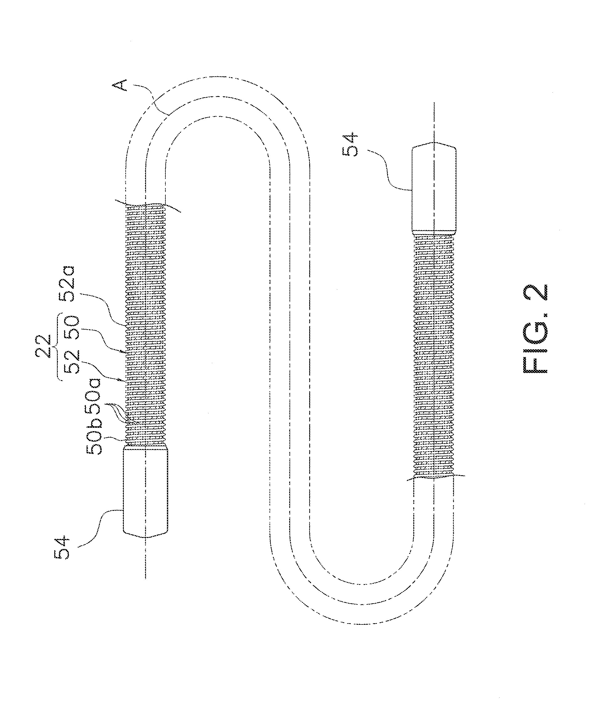
[0048]In the second embodiment, as seen in FIG. 7, a lacing cord 122 is illustrated. Here, the lacing cord 122 has a core wire 150, a protruding part 152 and a primer layer 153. The core wire 150 of the lacing cord 122 has a peripheral section 150b that is covered with a primer layer 153 as illustrated in FIG. 7. The protruding part 152 is spirally wound on the core wire 150 via the primer layer 153. The primer layer 153 is provided to enhance the adhesion of the core wire 150 to the protruding part 152 and to strengthen the adhesion of the protruding part 152.

Other Embodiments

[0049]Embodiments of the present invention were described above. However, the present invention is not limited to these embodiments, and various changes are possible in a scope of not deviating from the essence of the invention. In particular, the embodiments and modified examples described in the specification can be optionally combined according to the need to do so.

[0050](a) In the embodiments described abo...


PUM


Abstract

A lacing cord is used in an article to be laced that includes shoes, clothing and bags. The lacing cord basically includes a core wire and at least one protruding part. The core wire includes at least one wire member. The at least one protruding part is provided to a peripheral section of the core wire so as to intersect with an axial direction of the core wire and to protrude radially outward from the peripheral section of the core wire.

Description

CROSS-REFERENCE TO RELATED APPLICATIONS[0001]This application claims priority under 35 U.S.C. §119 to Japanese Patent Application No. 2013-003223, filed Jan. 11, 2013. The entire disclosure of Japanese Patent Application No. 2013-003223 is hereby incorporated herein by reference.BACKGROUND[0002]1. Field of the Invention[0003]This invention generally relates to a lacing cord used for daily necessities including shoes, clothing, and bags and shoes that use this lacing cord.[0004]2. Background Information[0005]Generally, a lacing cord is used in daily necessities including with shoes, clothing and bags. For example, a lacing cord is conventionally known in skating shoes in which the lacing cord is wound using a winding member (see, for example, Japanese Laid-Open Patent Publication No. 2010-148927). Also, a lacing cord wound on a winding member is conventionally known in sports shoes (see, U.S. Patent Application Publication No. 2011 / 0266384). The conventional lacing cord is guided to ...

Claims


Application Information

Patent Timeline
Patent Type & Authority Applications(United States)
IPC IPC(8): A43C1/06
CPCA43C1/06A43C11/165A45F3/00A45F3/04A45F2003/001Y10T24/37
Inventor SAKAUE, ATSUSHIKIRIMOTO, KANJI
Owner SHIMANO INC
Why Eureka
Try Eureka