Impact energy management method and system

a technology of energy management and energy management, applied in the field of impact energy management method and system, can solve the problems of large limitation of the adaptability of the foam, the inability of the foam to adapt to a wide range of impact energy, and the mismatch of the functional capability of the foam, so as to reduce the force of an impact

Active Publication Date: 2010-08-17
XENITH
View PDF88 Cites 136 Cited by
  • Summary
  • Abstract
  • Description
  • Claims
  • Application Information

AI Technical Summary

Benefits of technology

[0009]From this equation, it is apparent that one way to reduce the Force imparted to an object of fixed mass (m) is to prolong the time (t) over which the object changes velocity, thus reducing its acceleration.
[0039](a) placing a protective structure over a portion of the body to be protected, the protective structure being capable of reducing forces of an impact that are transferred through it to the body;

Problems solved by technology

This presents two major limitations.
First, relying on material properties severely limits the adaptability of the foam.
Foams can be customized to respond optimally to only a very specific range of impact energies, either by changing the density or geometry (thickness) of the foam, but foams are not able to adapt their response to a wide range of impact energies.
This can lead to a mismatch of the foam's functional capability to the impact energy, making the foam either “too soft” or “too hard” for the impact.
A foam that is too soft (not dense enough) for an impact will compress too quickly or “bottom out” and transmit too much force to the impacted body.
A foam that is too hard (too dense) for an impact will not compress enough and will decelerate the impacted body too quickly.
When foam becomes fully compressed under impact, it acts as a rigid body and loses its ability to absorb energy.
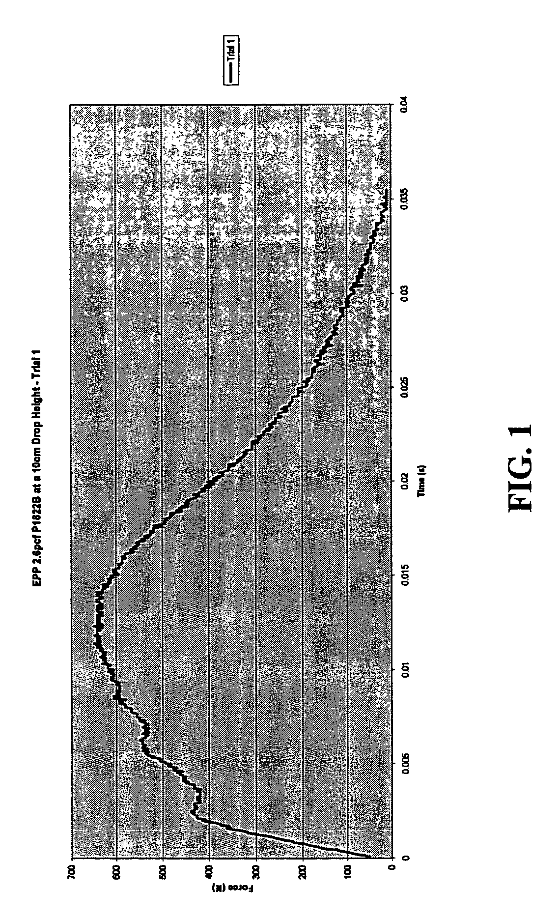
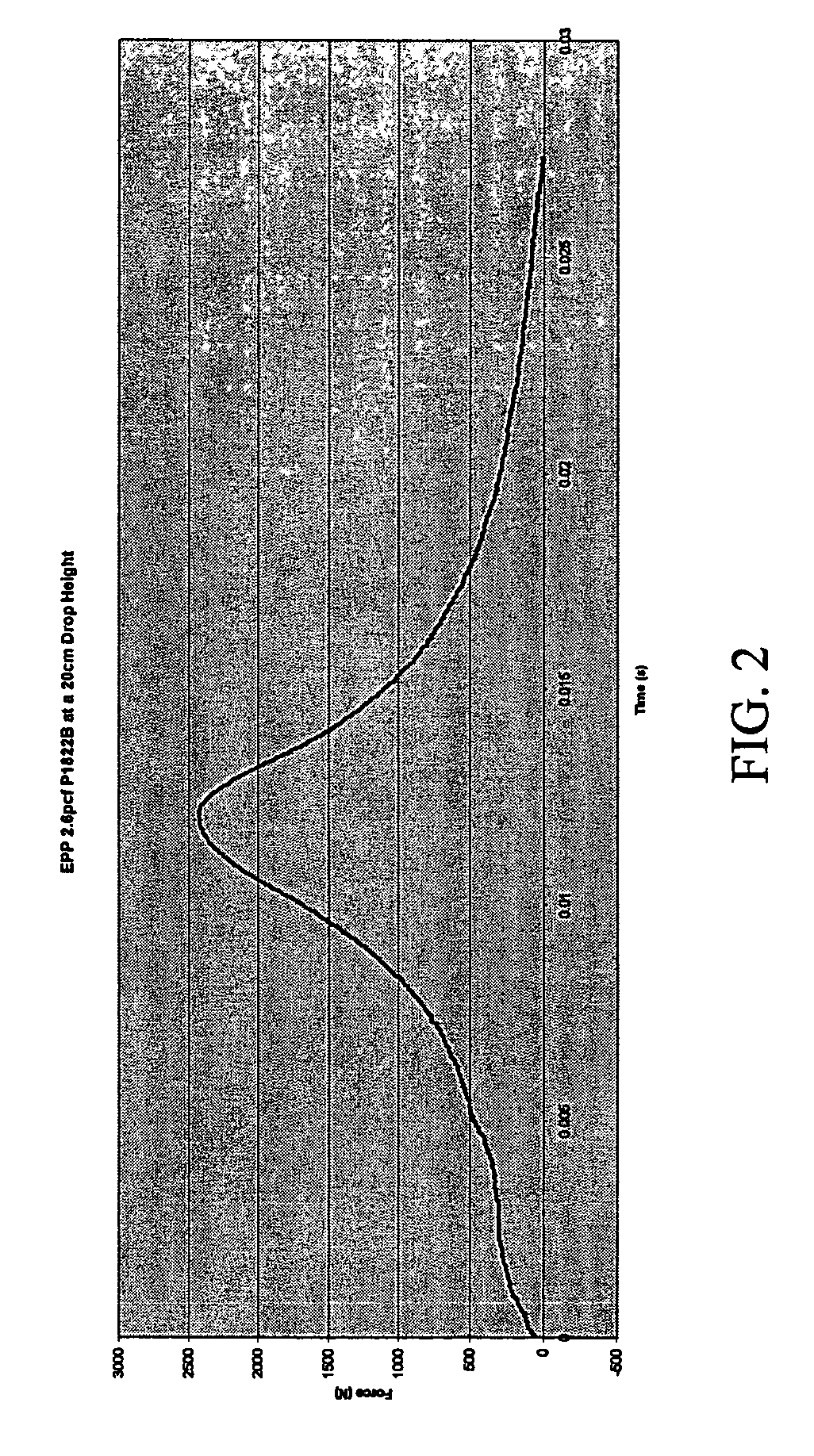
This curve demonstrates that the majority of the deceleration occurs in a brief period of time and distance, thus delivering a high peak force, which is the most damaging to the impacted body.
In addition, the potential for localized compression of the soft foam decreases the area over which the force may be transmitted, therefore potentially increasing the pressure and damage of the impact.
Due to potentially catastrophic consequences of bottoming out within a small area, soft foams cannot be used in situations that may involve moderate or high energy impacts.
Conversely, a foam can also be too hard (too dense) for a given impact.
If the foam is too hard, it will present too much resistance in the early phase of the impact, and will not compress enough (will not “ride-down” enough) to prolong the distance or time of impact.
These dense foams function primarily to spread the impact area and reduce pressure on the area, but can still lead to high forces.
Another problem with dense foams is the potential for high “rebound”, in which the foam temporarily stores impact energy in compression, then re-delivers it upon rebound.
Thus, dense foams are useful for reducing pressure of impacts, but their ability to significantly reduce peak force is limited.
Even when foams happen to be matched to the impact (which may occur by chance, or by specific engineering of foams to meet certain very specific energy level standards), they still have inherent limitations.
One major limitation is the inability of the foam to “ride-down” enough to prolong the distance and time of the impact.
Most foams will ride-down to a maximum of 60-70% of their original height, which limits the distance and time over which the impact occurs, and leads to higher peak forces.
This modification can serve to lower the peak forces, but due to the inherent properties of foam, which cause it to become progressively denser under compression, the curve is still hump- or bell-shaped, limiting the foam's ability to lower peak force.
Further, an increased thickness of foam may be cosmetically or practically unacceptable for certain applications, and may also increase the bulk and weight of the energy management system to unacceptable levels.
Given the properties of foam, once it is manufactured, it will have a certain energy level at which it performs “optimally,” but this performance still leaves great room for improvement, and outside of its optimal range the foam's function will be even worse, either being potentially too hard or too soft for a given impact.
Thus, foam lacks an ability to adapt to the potential for impacts of different energy levels.
This leads to the use of foams designed simply to perform best at a certain standard, or designed to prevent only the most critical forms of damage, but leaving other forms of damage poorly addressed. FIG. 4 of the drawing includes two Force / Time curves for a given foam generated in response to two different impact energies.
As is apparent from FIG. 4, the foam's performance declines with increased impact energy.
The second major limitation of foam is that all foams will show decline in function after repeated impacts.
Other foams, even though designed to be “multi-impact,” will also decline in function after repeated impacts.
This lack of durability can present practical as well as safety limitations with the use of foams. FIG. 5 of the drawing includes a series of Force / Time curves for successive impacts to a “multi-impact” foam illustrating the decline in the foam's performance with repeated impacts.
(a) limited adaptability;
(b) non-optimal impact energy management;
(c) tradeoff between energy absorbing ability and amount of material used; and
(d) poor durability.
While we have specifically focused on the limitations of foams, those skilled in the art will appreciate that other mechanisms of energy management may be employed, and that they may also be subject to the same or similar functional limitations as foam.

Method used


Image

  • Impact energy management method and system
  • Impact energy management method and system
  • Impact energy management method and system

Examples


Embodiment Construction

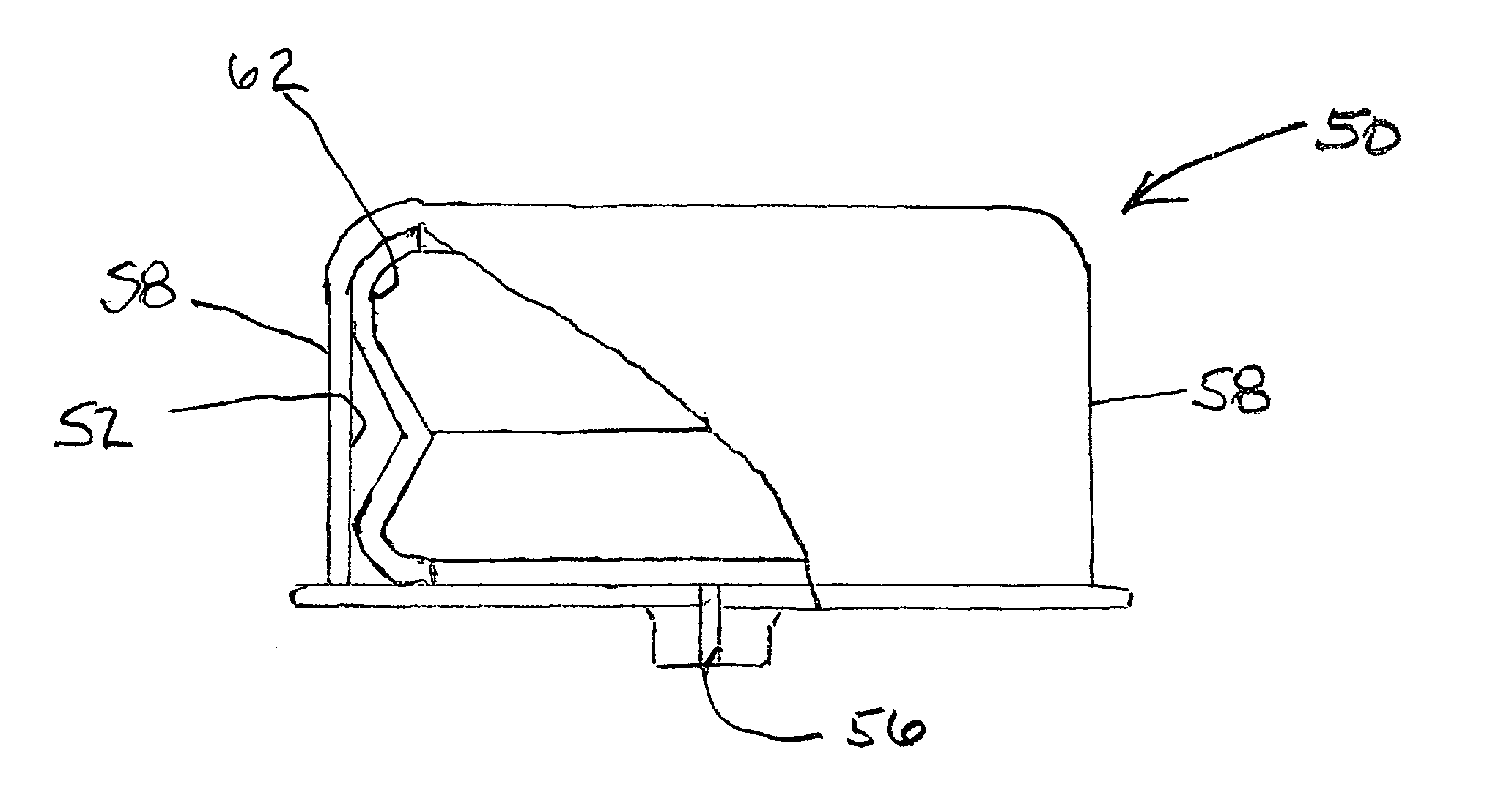
[0063]A compressible, impact-absorbing compressible cell 10 embodied in accordance with the invention is shown in FIGS. 6 and 7 of the drawing.

[0064]In the illustrative embodiment of FIGS. 6 and 7, the cell 10 is made from a thermoplastic material, such as a thermoplastic elastomer (TPE) material, formed into a thin-walled, hollow enclosure 12 with a top wall 14a and a bottom wall 14b and an orifice 16 through its bottom wall 14b. The side walls 18 of the cell 10 are oriented semivertically, such that they provide an initial resistance to an impact on the cell 10, but then strategically buckle outwardly to allow the fluid in the cell 10, in this case air, to manage the remainder of the impact by venting through the orifice 16, as indicated by the air flow arrow 20. The resilient properties of the thermoplastic material from which the cell 10 is fabricated, coupled with the refill of air through the orifice 16, allow the cell 10 to quickly return to its original shape after impact.

[0...


PUM

PropertyMeasurementUnit
angleaaaaaaaaaa
angleaaaaaaaaaa
Forceaaaaaaaaaa

Abstract

An impact-absorbing protective structure comprises one or more compressible cells. Each cell is in the form of a thin-walled plastic enclosure defining an inner, fluid-filled chamber with at least one small orifice through which fluid resistively flows. Each cell includes an initially resistive mechanism that resists collapse during an initial phase of an impact and that then yields to allow the remainder of the impact to be managed by the venting of fluid through the orifice. The initially resistive mechanism may be implemented by providing the cell with semi-vertical side walls of an appropriate thickness or by combining a resiliently collapsible ring with the cell. After the initially resistive mechanism yields to the impact, the remainder of the impact is managed by the fluid venting through the orifice. The cell properties can be readily engineered to optimize the impact-absorbing response of the cell to a wide range of impact energies.

Description

CROSS-REFERENCE TO RELATED APPLICATIONS[0001]The present application is a continuation-in-part application of PCT application no. US2006 / 005857, filed Feb. 16, 2006. The content of the above application is incorporated herein by reference.BACKGROUND OF THE INVENTION[0002]1. Field of the Invention[0003]This invention relates generally to an impact energy management method and system. More specifically, it relates to an impact energy management method and system which is designed to protect an impacted object or body from damage due to impacts and which has properties that are readily customized to provide optimum impact-attenuating responses over a wide range of impact energies.[0004]2. Background Information[0005]A. The Physics of Colliding Objects[0006]An object in motion possesses kinetic energy (KE), which is a function of its mass (m) and velocity (v), described by the equation:KE=½mv2  (1)[0007]When that object collides with another object, the energy is transferred, imparting ...

Claims


Application Information

Patent Timeline
Patent Type & Authority Patents(United States)
IPC IPC(8): A41D13/00
CPCA42B3/121B32B3/12B32B3/266B32B5/18F16F9/0481B32B27/40B32B27/065Y10T428/24562B32B2274/00B32B2307/558B32B2307/56
Inventor FERRARA, VINCENT R.
Owner XENITH
Why Eureka
Try Eureka