Electrical connecting member for secondary battery

a secondary battery and electric connection technology, applied in the direction of battery, cell components, coupling device connections, etc., can solve the problems of low safety in abnormal conditions, battery pack lithium secondary batteries, and difficulty in arranging cylindrical batteries in a stacked structure, so as to facilitate and simply manufacture the connection member, the effect of maximizing the contact area

Active Publication Date: 2012-10-16
LG ENERGY SOLUTION LTD
View PDF25 Cites 12 Cited by
  • Summary
  • Abstract
  • Description
  • Claims
  • Application Information

AI Technical Summary

Benefits of technology

[0028]Specifically, it is an object of the present invention to provide a connection member for secondary batteries that is capable of stably achieving the electrical connection between two or more secondary battery cells without performing a soldering or welding process, which requires a complicated working process, and constructed in a specific structure in which the electrical connection thereof is possible, an assembly process is easily performed, and the connection member is freely attached and detached as needed.
[0128]Preferably, the connection member is used especially for cylindrical battery cells. In this case, the specific regions of the connection member are generally constructed in a concentric circle structure, which corresponds to the shape of the electrode terminal of each cylindrical battery cell, with the result that the contact area therebetween is maximized.

Problems solved by technology

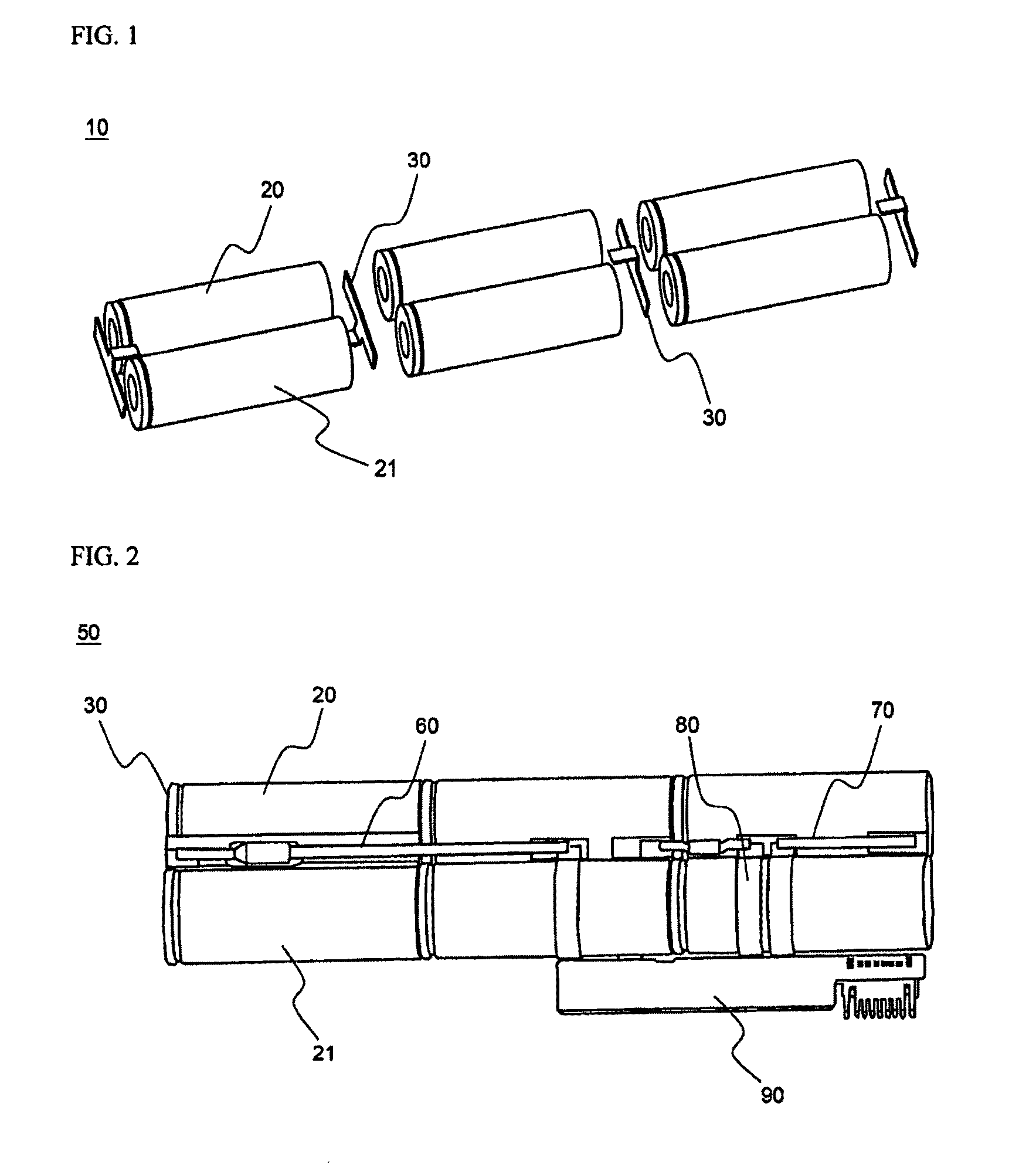
However, it is difficult to arrange the cylindrical batteries in a stacked structure due to the external shape of the cylindrical secondary batteries.
Generally, a battery pack using secondary batteries as unit cells is repeatedly charged and discharged during the use of the battery pack, and the battery pack uses lithium secondary battery, which exhibits low safety in abnormal conditions, such as external impact, dropping, penetration of a needle-shaped body, overcharge, overcurrent, etc., as a unit cell.
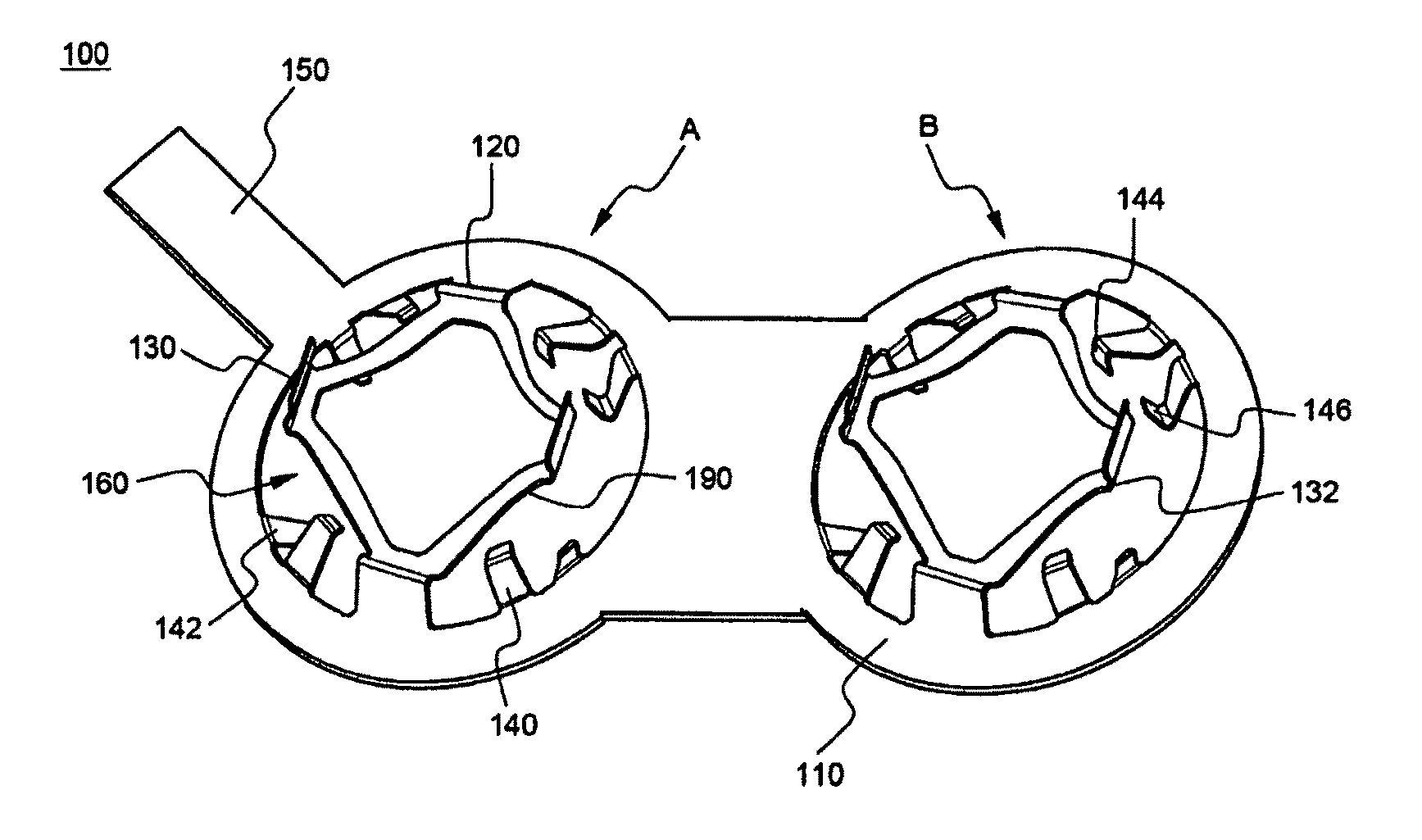
Consequently, when the connection state of the corresponding region is variable, for example, the resistance value of the terminal connection region changes due to vibration, the detected information is inaccurate, and therefore, the safety element cannot perform the desired process.
However, the welding or soldering process between the battery cells has the following problems.
As a result, the production process is complicated, and the production costs increase, whereby the production efficiency lowers.
Also, a short circuit may occur at the welded region, due to the vibration generated from the battery pack or external impact applied to the battery pack, at the time of directly welding or soldering the battery cells.
In addition, electrical or thermal damage may be caused between the battery cells and the connection members, whereby the safety of the batteries is threatened, and the defective product rate increases.
Furthermore, when some of the battery cells become defective, during the manufacturing or use of the battery cells, all the battery cells constituting the battery pack must be discarded.
Consequently, there is a high necessity for a technology that is capable of substituting for the connection method based on such welding or soldering, which threatens the safety of the batteries and requires a complicated working process, and, at the same time, reusing the remaining battery cells, although some of the battery cells are defective, while stably securing the connection structure between the battery cells.
However, the above-mentioned technologies have a problem in that it is required for connection members to exhibit elasticity enough to fix the battery cells and stably connect electrode terminals to one another, and therefore, connection members exhibiting low elasticity are limited in use.
Especially, the technology using the conduction coils has problems in that the sectional area of a wire constituting each coil is small, and the connection length of the wire is relatively large, whereby the electrical resistance increases.
The increase of the electrical resistance causes power loss and increases the amount of heat generated, whereby the stable connection between the batteries may be obstructed.
Also, for the technology using the metal plates that are bent to have elasticity, the metal plates may lose their elasticity or break when an excessive force is applied to the metal plates at the time of inserting the battery cells into the pack case, or when the metal plates are repeatedly used, with the result that, when external impact is applied to the battery cells, the battery cells may be separated from the pack case or the electrical connection between the battery cells may be cut off.
Furthermore, the above-mentioned connection member is limited to apply to the previously described secondary battery pack due to the variable connection state at the corresponding region.
However, the provision of the partitions increases the size of the battery pack, which is far from the latest tendency to pursue the reduction in size, weight, and thickness.
However, the operating conditions of the battery cells mounted in the receiving parts divided by the partitions may be different from each other for the respective receiving parts, when external impact is applied to the battery pack, through the provision of the partitions.
In this method, however, a material, such as polymer resin, for the pack case is slowly deformed by stress during the use of the pack case for a long period of time, which is called a creep phenomenon.
Consequently, excessively high elastic pressing force of the connection members causes the occurrence of stress at the pack case, which leads to the creep phenomenon.
As a result, the distance between the battery cells gradually increases, and therefore, the electrical connection between the battery cells is unstable.
This phenomenon may be serious especially for a device of which the long-term use is required.
Consequently, the connection method based on the primary batteries cannot be applied to a battery pack, based on secondary batteries, of which the long-term use is required through repeated charge and discharge, without any modification.
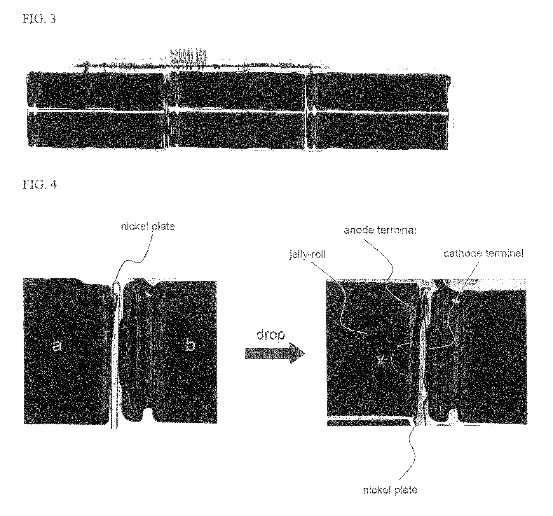
On the other hand, since the jelly-roll directly faces the inner bottom of the container, the anode terminal (i.e., the bottom of the container) is deformed by an external force, with the result that a short circuit may occur between electrode plates of the jelly-roll.
In a battery pack including a plurality of battery cells, such a short circuit causes a very serious problem in the aspect of the safety.

Method used


Image

  • Electrical connecting member for secondary battery
  • Electrical connecting member for secondary battery
  • Electrical connecting member for secondary battery

Examples


Embodiment Construction

[0160]Now, preferred embodiments of the present invention will be described in detail with reference to the accompanying drawings. It should be noted, however, that the scope of the present invention is not limited by the illustrated embodiments.

[0161]FIGS. 6 and 7 are perspective views typically illustrating a process for assembling a battery pack according to a preferred embodiment of the present invention.

[0162]Referring to these drawings, the battery pack 400 is constructed in a structure in which a plurality of cylindrical battery cells 302, 304, 306, and 308 are electrically connected to one another via predetermined connection members 100 and 102 in a pack case 200 having no partition.

[0163]Specifically, two kinds of connection members 100 and 102 and four cylindrical battery cells 302, 304, 306, and 308 are located in a receiving part of the pack case 200, while the four cylindrical battery cells 302, 304, 306, and 308 are brought into tight contact with one another, such th...


PUM

PropertyMeasurementUnit
heightaaaaaaaaaa
angleaaaaaaaaaa
angleaaaaaaaaaa

Abstract

Disclosed herein is a connection member for secondary batteries to achieve the electrical connection in a battery pack including two or more cylindrical secondary batteries in a physical contact manner, the connection member including an outer circumferential contact part contacting an electrode terminal of a lower battery cell along the outer circumferential region of the electrode terminal of the lower battery cell, such that the outer circumferential contact part can be electrically connected to the electrode terminal of the lower battery cell in a surface contact manner, for minimizing the change of resistance at the contact region against an external force and restraining a possibility that the electrode terminal of the lower battery cell is depressed, and a central contact part contacting an electrode terminal of an upper battery cell or the central region of a sidewall of the battery pack for providing an elastic contact force to the entire connection member mounted between the electrode terminals of the respective battery cells or between the electrode terminals of the battery cells and the sidewall of the battery pack.

Description

FIELD OF THE INVENTION[0001]The present invention relates to an electric connection member for secondary batteries, and, more particularly, to a connection member for secondary batteries to achieve the electrical connection in a battery pack including two or more cylindrical secondary batteries in a physical contact manner, the connection member including an outer circumferential contact part contacting an electrode terminal of a lower battery cell along the outer circumferential region of the electrode terminal of the lower battery cell, such that the outer circumferential contact part can be electrically connected to the electrode terminal of the lower battery cell in a surface contact manner, for minimizing the change of resistance at the contact region against an external force and restraining a possibility that the electrode terminal of the lower battery cell is depressed, and a central contact part contacting an electrode terminal of an upper battery cell or the central region...

Claims


Application Information

Patent Timeline
Patent Type & Authority Patents(United States)
IPC IPC(8): H01R33/00H01M50/503H01M50/516H01M50/522
CPCH01M2/105H01M2/204H01M2/206H01M2/202H01R13/2464H01M50/213H01M50/503H01M50/516H01M50/522Y02E60/10H01M2220/30
Inventor KWON, GI-HWANCHO, YONGHOBANG, SEUNGHYUNLEE, HAKJUNKWON, HOSANG
Owner LG ENERGY SOLUTION LTD
Why Eureka
Try Eureka