Fuel supply system and vehicle

a technology of fuel supply system and fuel supply system, which is applied in the direction of liquid fuel feeder, machine/engine, combustion air/fuel-air treatment, etc., can solve the problems of inability to provide a compact arrangement, further complications and inefficiencies, and the supply of lean mixture to the engine, so as to improve the fuel atomization effect and improve the performance of the engin

Active Publication Date: 2009-12-29
YAMAHA MOTOR CO LTD
View PDF81 Cites 12 Cited by
  • Summary
  • Abstract
  • Description
  • Claims
  • Application Information

AI Technical Summary

Benefits of technology

[0012]Thus, one aspect of the present invention comprises the recognition that the structure shown in FIG. 13 creates a bubble over phenomenon, which is not adequately addressed by suppressing fuel supply or movement of the fuel injector closer to the opening of the air intake passage. An object of the present invention is to provide a fuel supply system that will result in better fuel atomization such that engine performance can be improved without restricting fuel supply when an engine is at the high speed and high load mode of operation.
[0013]Thus, as will be described below, one feature of certain embodiments of the present invention is the shape of an aperture whose inner surface on the air cleaner side in the air intake path is so formed as to be continuous to the bottom surface of the air cleaner so that the likelihood can be reduced of fuel clogging on the bottom surface of the air cleaner.
[0014]Another aspect of the present invention is directed to a fuel supply system including: an air intake chamber including an air introduction passage for guiding air; an air intake path including an aperture that opens toward inside of the air intake chamber for guiding the air in the air intake chamber from the aperture to an engine; and an injector for injecting fuel between the air introduction passage and the aperture. In the air intake path, an inner surface of the aperture is structured continuous to a bottom surface of the air intake chamber. With such a structure, the fuel splashed over the bottom surface of the air intake chamber is less likely to pool because it flows into the air intake path. The flow results because the inner surface of the aperture of the air intake path serves to direct the air in the air intake chamber to the engine and is formed generally continuous with the bottom surface of the air intake chamber. Accordingly, the amount of fuel coming from the injector need not be suppressed to avoid bubble over and more flexibility can be used in placement of the injector relative to the aperture of the air intake path. In addition, because the fuel is injected between the air introduction passage for guiding the air into the air intake chamber and the aperture of the air intake path, the fuel can be better atomized with the air intake chamber. This improves atomization of fuel injected from the injector, and the engine performance can be improved when then engine is operating at high speeds and high loads.
[0015]Another aspect of the present invention involves an air intake chamber whose bottom surface is sloped down toward the outer edge of the aperture of the air intake path. With such a structure, when a large amount of fuel is splashed over the bottom surface of the air intake chamber, the fuel will drip into the air intake path such that the fuel is less likely to pool within the air intake chamber. Moreover, the air flow through the air intake chamber can better vaporize the fuel and carry it to the engine for combustion. The slope can be 45 degrees or less or 30 degrees or less. Such a construction allows a sufficient change in cross sectional area within the induction system such that rarification waves can be reflected back into the induction system when they arrive from the intake port. The rarification waves can be used to improve engine volumetric efficiency by packing the combustion chamber with the air-fuel charge.

Problems solved by technology

Such a construction undesirably places the fuel injector relatively close to the combustion chamber.
While such a fuel supply system provides improved fuel atomization, it fails to provide a compact arrangement.
Suppressing the amount of fuel coming from the upstream injector may result in a lean mixture being supplied to the engine.
Thus, both suggestions to correct bubble over lead to further complications and inefficiencies.

Method used


Image

  • Fuel supply system and vehicle
  • Fuel supply system and vehicle
  • Fuel supply system and vehicle

Examples


Embodiment Construction

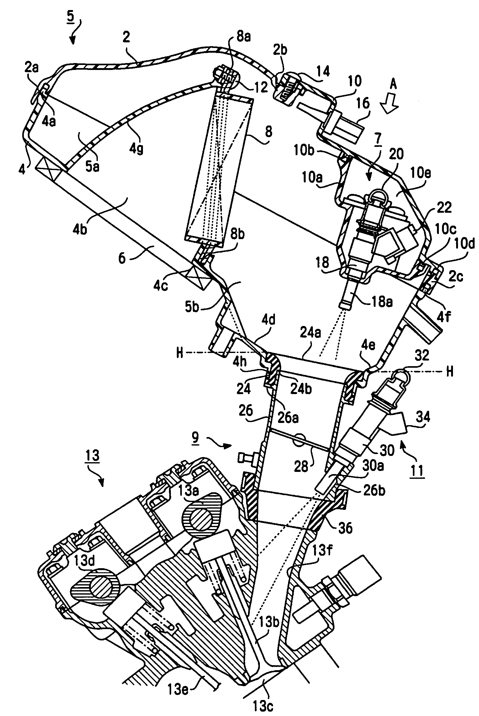
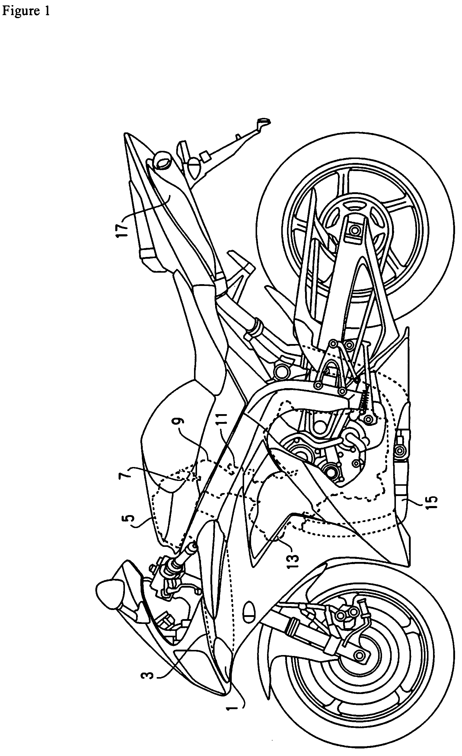
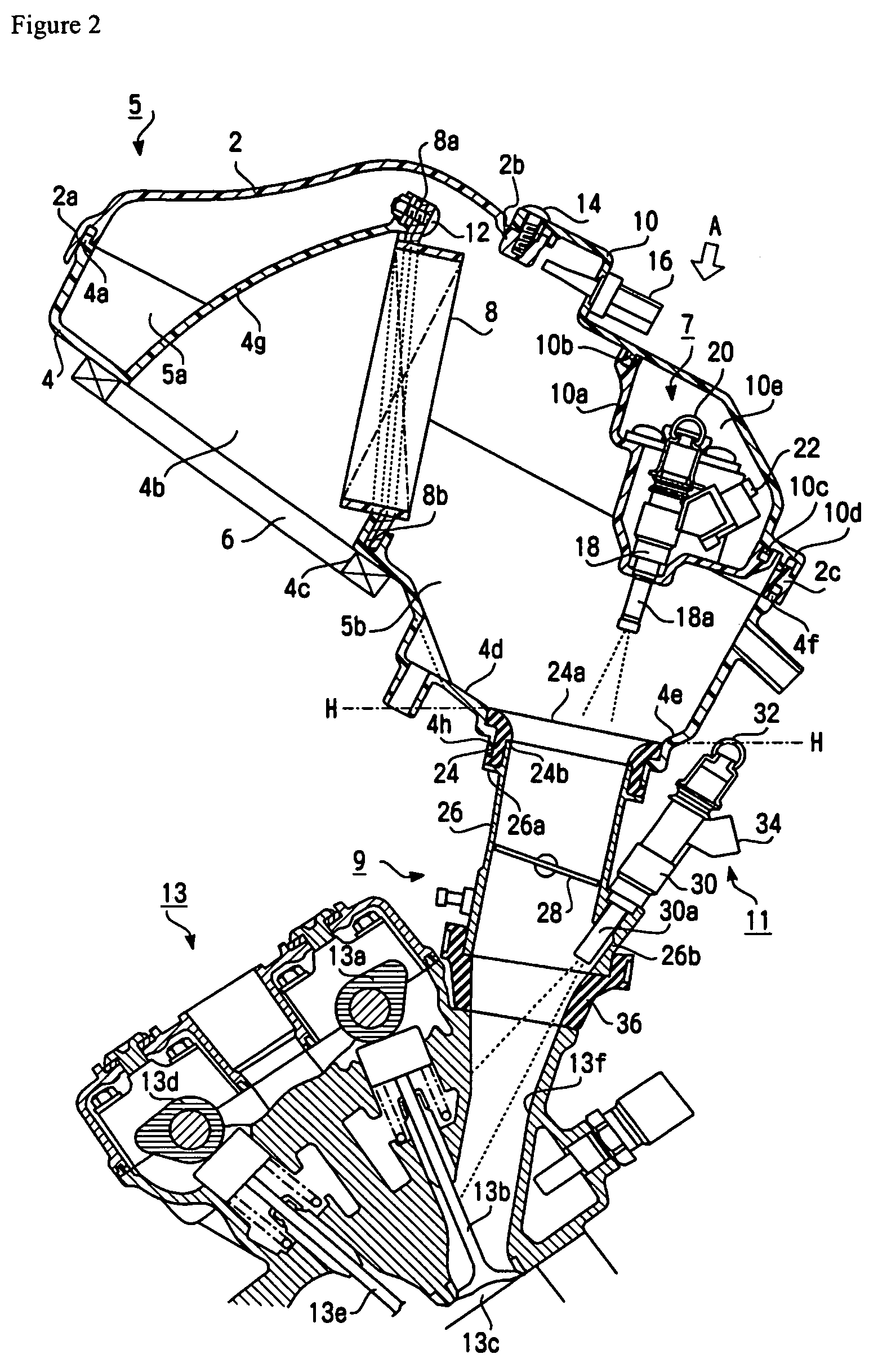
[0032]With reference initially to FIG. 1, an exemplary vehicle is shown in side view. The vehicle can have a fuel supply system that is arranged and configured in accordance with certain features, aspects and advantages of a first embodiment of the present invention. While the illustrated vehicle is a two-wheeled motorcycle, the fuel system can find utility with other types of vehicles and engines, including those used in applications other than vehicular applications.

[0033]With continued reference to FIG. 1, the front of the vehicle is positioned to the left side of the figure while the rear of the vehicle is positioned to the right side of the figure. Air captured by an air induction port 1 goes through an induction duct 3 and reaches an air cleaner 5. The air is then purified by the air cleaner 5, and the purified air is sucked into an air intake path 9 where it is mixed with fuel coming from an upstream injector unit 7. As used herein, the term “upstream injector unit” means a f...


PUM


Abstract

A fuel supply system has an air chamber that contains a fuel injector. At least one aperture is formed in a substantially lowermost portion of a lower surface of the air chamber. The aperture and the lower surface have a generally uninterrupted or smooth transition or interface.

Description

RELATED APPLICATIONS[0001]The present invention claims the priority benefit of Japanese Patent Application No. 2004-083393, filed on Mar. 22, 2004, which is hereby incorporated by reference in its entirety.BACKGROUND OF THE INVENTION[0002]1. Field of the Invention[0003]The present invention generally relates to fuel supply systems and vehicles. More particularly, the present invention relates to a fuel supply system for supplying fuel to an engine, and a vehicle equipped with the fuel supply system.[0004]2. Description of the Related Art[0005]A conventional fuel injector generally is located downstream (in an airflow direction) of a throttle valve. In most arrangements, an air cleaner is positioned on an opposite side of the throttle valve from the fuel injector. Thus, air is drawn into a combustion chamber of an engine through the air cleaner, across the throttle valve and past the fuel injector.[0006]Such a construction undesirably places the fuel injector relatively close to the ...

Claims


Application Information

Patent Timeline
Patent Type & Authority Patents(United States)
IPC IPC(8): F02M25/00F02M35/10F02M35/024F02D9/10F02M35/112F02M35/16F02M61/14F02M69/00F02M69/04
CPCF02M35/10039F02M35/10052F02M35/10072F02M35/10144F02M69/044F02M35/10216F02M35/10354F02M61/145F02M69/043F02M35/10177F02D9/1095F02M35/024F02M35/112F02M35/162
Inventor KOIDE, MITSUTOSIKONAKAWA, TSUGUNORINISHIZAWA, KAZUYA
Owner YAMAHA MOTOR CO LTD
Why Eureka
Try Eureka