

Fuel Injector
a fuel injector and fuel injection technology, applied in the direction of machines/engines, combustion types, lighting and heating apparatus, etc., can solve the problems of complex manufacturing process of the orifice plate with its outlet opening, and achieve the effect of reducing the emissions of internal combustion engines, reducing the exhaust emissions during this period, and low emission values
- Summary
- Abstract
- Description
- Claims
- Application Information
AI Technical Summary
Benefits of technology
Problems solved by technology
Method used
Image

Examples
Embodiment Construction
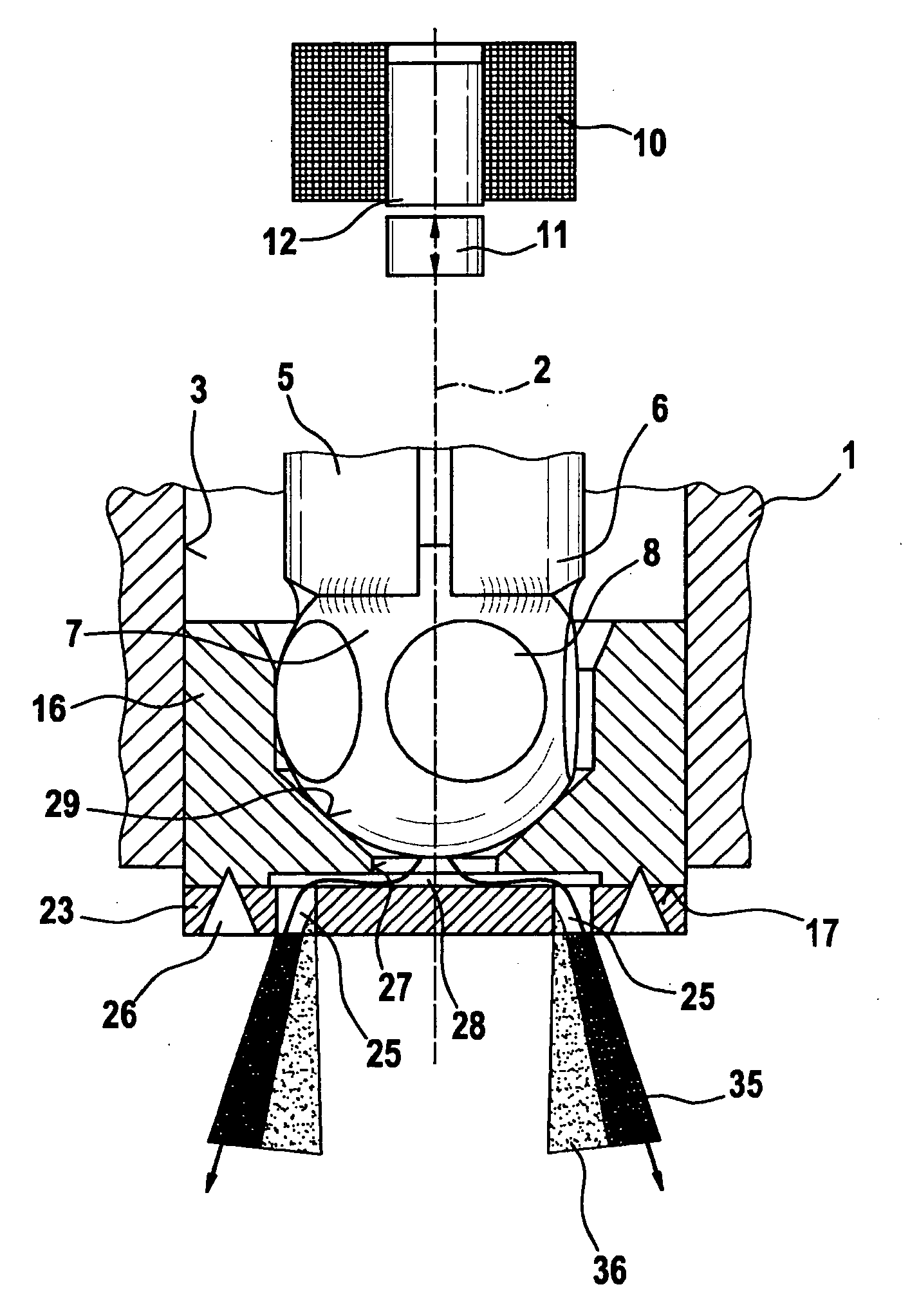
[0018]As an exemplary embodiment, FIG. 1 shows a partial view of a valve in the form of a fuel injector for fuel injection systems of mixture-compressing internal combustion engines having externally supplied ignition. The fuel injector has a tubular valve seat support 1, indicated only schematically, which constitutes part of a valve housing and in which a longitudinal opening 3 is formed concentrically with a longitudinal valve axis 2. Situated in longitudinal opening 3 is, for example, a tubular valve needle 5, whose downstream end 6 is fixedly connected to a, for instance, spherical valve closure member 7, on whose periphery, for example, five flattened regions 8 are provided to enable the fuel to flow past.
[0019]The fuel injector is actuated in a known manner, e.g. electromagnetically. A schematically sketched electromagnetic circuit, which includes a solenoid coil 10, an armature 11 and a core 12, is used for axial displacement of valve needle 5, and thus for opening the fuel ...
PUM
 Abstract
Description
Claims
Application Information