Combustion Chamber

a combustion chamber and chamber technology, applied in combustion regulation, combustion failure safety, fuel supply regulation, etc., can solve the problems of affecting the economic affecting the efficiency of the gas turbine, and extinction of the same, so as to reduce the pulsation tendency of the burner, the effect of reducing the risk of pulsation and reducing the emission valu

Inactive Publication Date: 2007-09-27
ANSALDO ENERGIA SWITZERLAND AG
View PDF18 Cites 4 Cited by
  • Summary
  • Abstract
  • Description
  • Claims
  • Application Information

AI Technical Summary

Benefits of technology

[0009] Another aspect of the present invention involves the general idea of providing measuring devices that are suitable in the case of a combustion chamber, in particular of a combustion chamber of a gas turbine, with a number of burners and which determine burner-specific data from which a computing and control device can calculate correlation values that permit the burners to be divided into pulsation-prone and non-pulsation-prone burners. If the computing and control device specifies a burner as pulsation-prone on the basis of the values measured in the combustion chamber, more fuel is fed to this burner and the risk of pulsation is thereby reduced. The detection of the data of the combustion chamber for judging whether a burner is a critical one, that is to say prone to pulsation, is performed on the one hand via an optical measuring device that is assigned to each burner and is designed for detecting chemiluminescent radiation and, on the other hand, via a further measuring device in the form of a pressure sensor for detecting a combustion chamber pressure. The burners themselves are connected to a fuel supply via controllable fuel valves. In order to process the data incoming from the optical measuring devices and the pressure sensor, the computing and control device is connected to them on the input side. On the output side, the computing and control device is connected to the controllable fuel valves, and this enables at least the burners prone to pulsation to be controlled via a changed fuel feed. The computing and control device is designed, furthermore, in such a way that it calculates a correlation from the chemiluminescent radiation values and the pressures, and determines the burner or a burner group with the highest correlation. The associated fuel valve(s) of the burners thereby determined are thereupon opened by the computing and control device and the pulsation tendency of the burners is thereby reduced. The combustion chamber according to the invention can therefore be used for early detection of burners prone to pulsation, that is to say critical burners, and to take suitable countermeasures. This permits an overall lean operation of the combustion chamber and therefore low emission values, it being possible at the same time effectively to exclude an extinction of the flame in the combustion chamber. This firstly increases the efficiency, and secondly the cost effectiveness of the gas turbine equipped with the combustion chamber according to the invention.
[0010] It is expedient for the optical measuring devices and / or the pressure sensor and / or the fuel valves to be connected to the computing and control device in a communicating fashion via a BUS, such as a CAN BUS. Such CAN BUS systems enable a comprehensive data exchange and a corresponding communication between the different components that are connected and mutually networked. In particular, such CAN BUS systems create far reaching networking possibilities such that it is also conceivable to be able to connect further units for measuring, detecting or processing data, and to connect devices designed for controlling specific parameters.
[0011] In a preferred embodiment of the solution according to the invention, the optical measuring devices each have an optical fiber. This offers the advantage that the optical measuring device need not be arranged directly in the combustion chamber, but needs to be connected to the combustion chamber only via such an optical fiber. Moreover, the space requirement of such an optical fiber in the combustion chamber is minimal, for which reason it can also be installed at sites offering little space. Moreover, a sensor system of the optical measuring device is not exposed directly to the high temperatures prevailing in the combustion chamber, and this has a positive effect on the service life of the optical measuring devices.

Problems solved by technology

However, this can give rise to a conflict of aims, since it is possible, particularly in the case of a lean operation of the gas turbine, for the flame in the combustion chamber to pulsate, and this leads to extinction of the same in the most unfavorable case.
For the purpose of being able to prevent pulsation of the flame in the combustion chamber, and thereby possible extinction of the flame, it is important to detect pulsation-prone burners as early as possible and to take appropriate countermeasures, since, as mentioned above, restarting the gas turbine because of an extinction of the flame is very complicated and expensive, and the economic efficiency of the gas turbine is negatively influenced thereby.

Method used


Image

  • Combustion Chamber
  • Combustion Chamber

Examples


Embodiment Construction

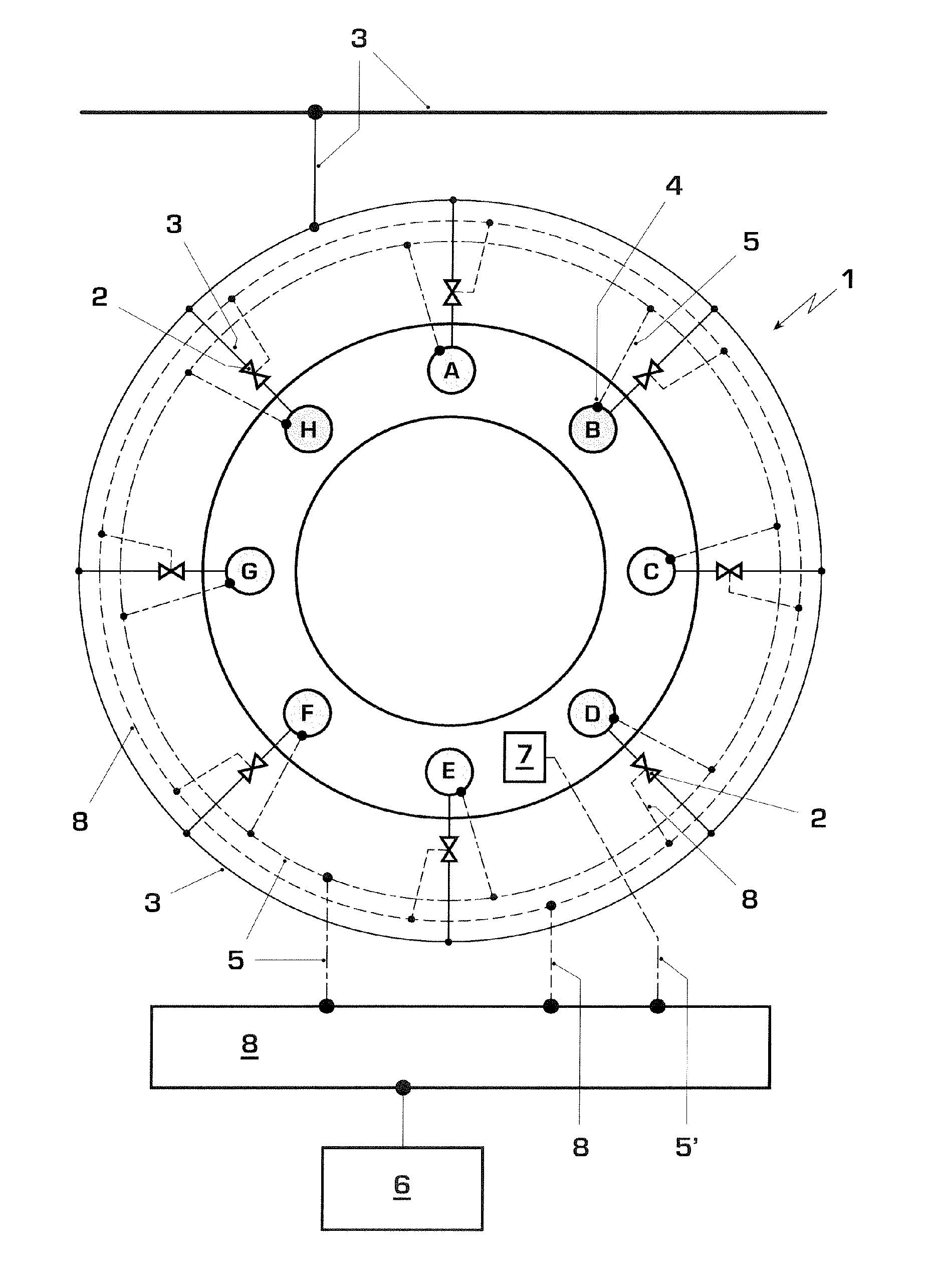
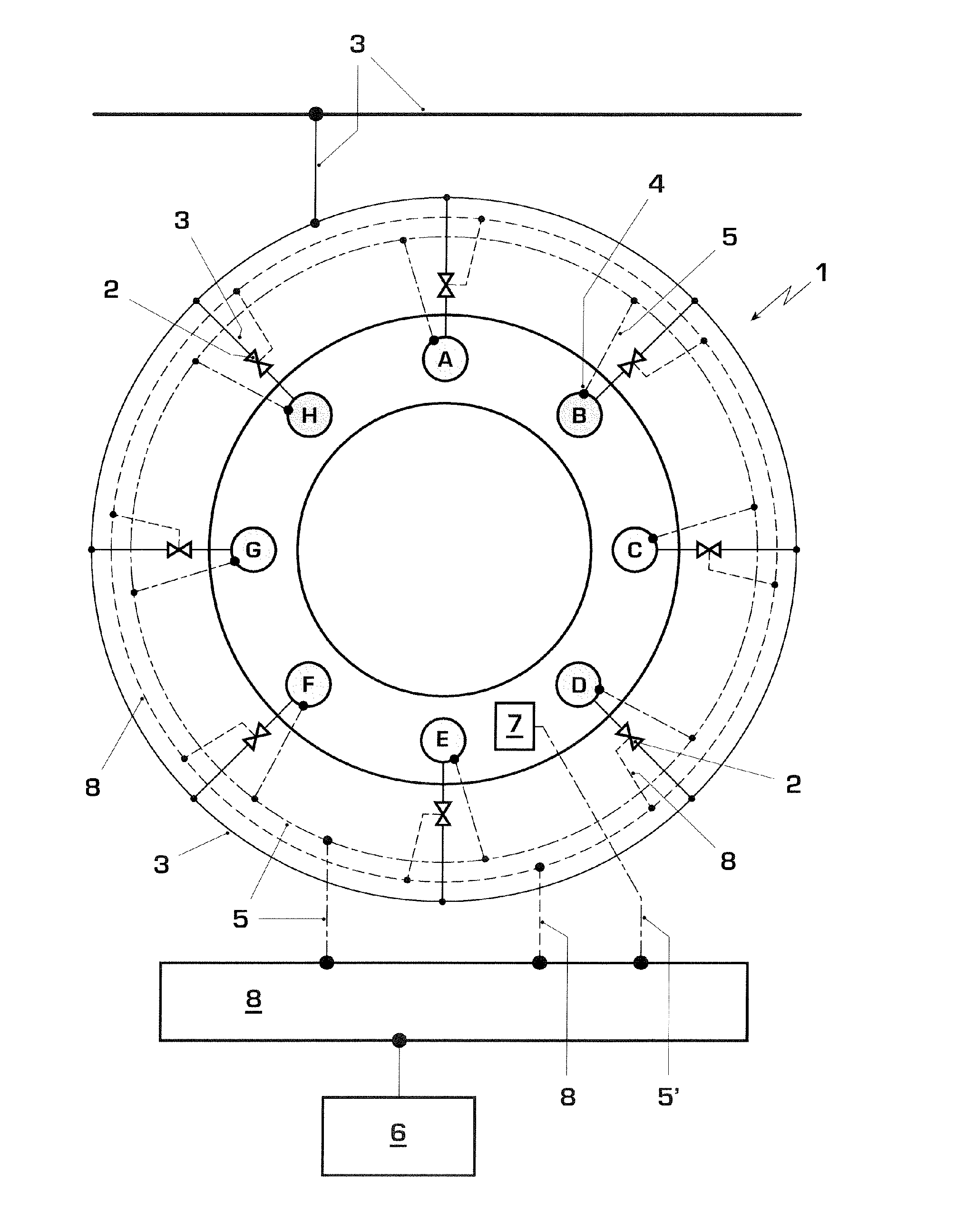
[0015] In accordance with the drawing FIGURE, a highly schematic combustion chamber 1, for example as used in a gas turbine, has a number of burners A to H that are connected via controllable fuel valves 2 to a fuel supply 3, for example a fuel line. The number of the burners A to H, here eight, is to be understood as purely exemplary, and so the invention is also intended to comprise a fuel chamber 1 with more than eight or less than eight, but at least two burners.

[0016] The burners A to H are arranged, for example, in an annular fashion and each have at least one optical measuring device 4 for detecting chemiluminescent radiation, in particular for detecting an OH chemiluminescence. The optical measuring devices 4 are connected to a computing and control device 6 via corresponding signal lines 5, in particular via a CAN bus 8. Moreover, the fuel valves 2, 2′ can also be connected to the computing and control device 6 via corresponding control lines 5″ via the CAN BUS 8. The opti...


PUM


Abstract

A combustion chamber (1), in particular in a gas turbine, has at least two burners (A-H) that are connected to a fuel supply (3) via controllable fuel valves (2′ and 2). Each burner (A to H) is assigned at least one optical measuring device (4) for detecting chemiluminescent radiation, and the combustion chamber (1) is assigned a pressure sensor (7) for detecting a combustion chamber pressure. The optical measuring device (4) and the pressure sensor (7) are connected to a computing and control device, which calculates a correlation value from the incoming measured values. A high correlation value signifies that the associated burner is prone to pulsation. The computing and control device (6) is designed in such a way that it determines the burner or a burner group with the highest correlation and controls the associated fuel valve(s) in such a way that more fuel is fed to the respective burner or the respective burner group, and the pulsation tendency thereof is thereby reduced.

Description

[0001] This application claims priority under 35 U.S.C. § 119 to German application number 10 2006 015 230.1, filed 30 Mar. 2006, the entirety of which is incorporated by reference herein. BACKGROUND [0002] 1. Field of the Invention [0003] The invention relates to a combustion chamber, in particular to one in a gas turbine, having at least two burners that are connected to a fuel supply via controllable fuel valves. [0004] 2. Brief Description of the Related Art [0005] Gas turbines are used, for example, for the generation of electrical energy in power plants, where they drive generators. Such turbines usually have a power of more than 50 MW and are designed, in particular, for stationary continuous operation. In order to be able to operate the gas turbine economically and with low pollutant emissions, in particular NOx, the aim should be to operate it in a lean fashion, that is to say with as little fuel as possible, and, on the other hand, to avoid extinguishing the burner, since ...

Claims


Application Information

Patent Timeline
Patent Type & Authority Applications(United States)
IPC IPC(8): F23N5/08
CPCF23N1/002F23N5/08F23N5/082F23N5/16F23R3/28F23N2025/04F23N2031/06F23N2037/02F23N2023/10F23N2223/10F23N2225/04F23N2231/06F23N2237/02
Inventor NI, ALEXANDERBELLUCCI, VALTERFLOHR, PETERSCHUERMANS, BRUNOTOQAN, MAJEDHAFFNER, KEN-YVES
Owner ANSALDO ENERGIA SWITZERLAND AG
Why Eureka
Try Eureka