
Fuel nozzle, combustion chamber and aircraft engine

An aero-engine and fuel nozzle technology, applied in the field of aero-engines, can solve the problems of weak swirling aerodynamic force, weakened shearing effect, poor fuel atomization effect, etc., achieve good fuel atomization effect and improve stability

Active Publication Date: 2019-06-28
AECC HUNAN AVIATION POWERPLANT RES INST
View PDF3 Cites 10 Cited by
  • Summary
  • Abstract
  • Description
  • Claims
  • Application Information

AI Technical Summary

Problems solved by technology

In the state of low engine power, the air pressure drop in the combustion chamber is very small, the aerodynamic force of the swirl flow is weak, the shearing effect is greatly weakened, and the fuel atomization effect is poor, which is very unfavorable to the engine's ignition and start and lean fuel flameout stability.

Method used


Image

  • Fuel nozzle, combustion chamber and aircraft engine
  • Fuel nozzle, combustion chamber and aircraft engine
  • Fuel nozzle, combustion chamber and aircraft engine

Examples


Embodiment Construction

[0064] Example embodiments will now be described more fully with reference to the accompanying drawings. Example embodiments may, however, be embodied in many forms and should not be construed as limited to the embodiments set forth herein; rather, these embodiments are provided so that this disclosure will be thorough and complete, and will fully convey the concept of example embodiments to those skilled in the art. The same reference numerals in the drawings denote the same or similar structures, and thus their detailed descriptions will be omitted.

[0065]Although relative terms such as "upper" and "lower" are used in this specification to describe the relative relationship of one component of an icon to another component, these terms are used in this specification only for convenience, for example, according to the drawings Directions for the example described. It will be appreciated that if the illustrated device is turned over so that it is upside down, then elements ...


PUM


Abstract

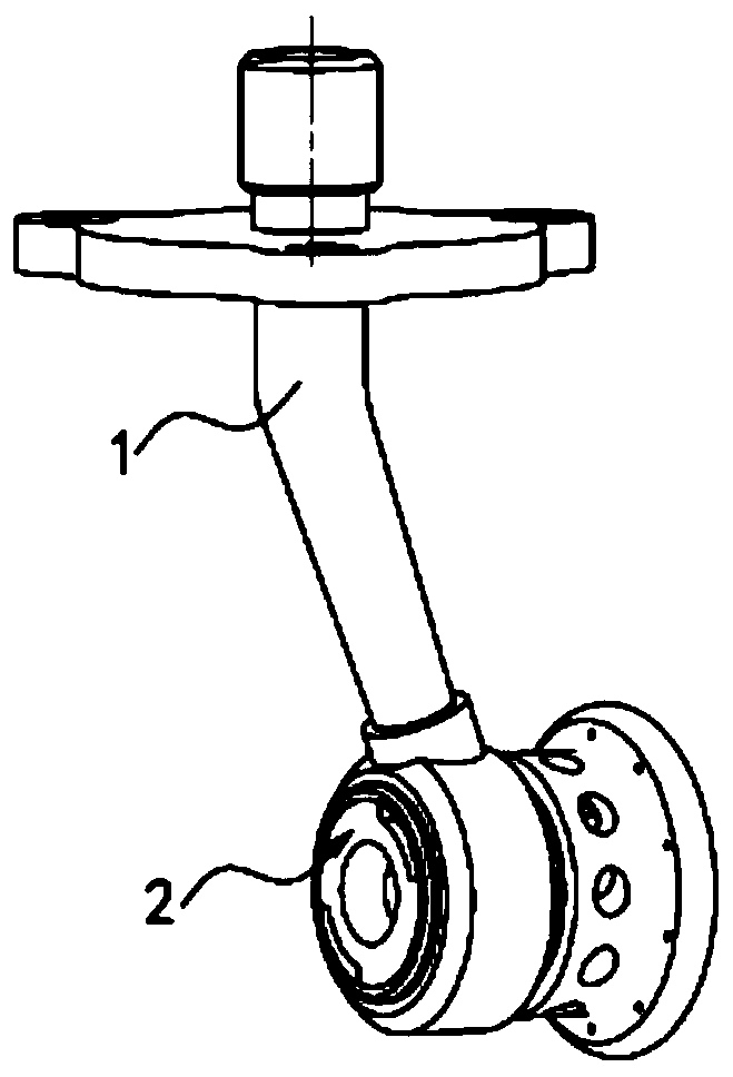
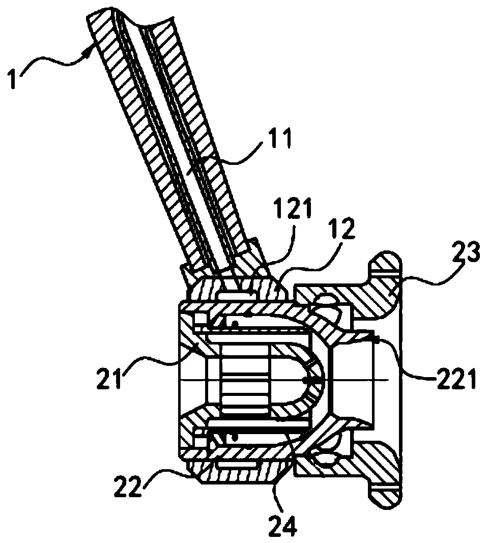
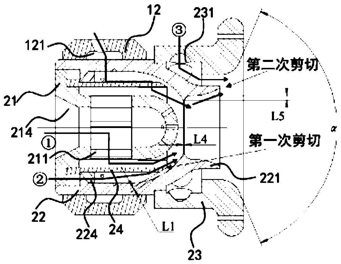
The invention provides a fuel nozzle, a combustion chamber and an aircraft engine. The fuel nozzle comprises a nozzle body and a nozzle rod, wherein the nozzle rod is used for conveying fuel to the nozzle body; the nozzle body comprises a first swirl component with a first swirl structure, second swirl components with second swirl structures and third swirl components with third swirl structures;the second swirl components surround the first swirl component in an interval mode, and the first swirl component has a Venturi structure; the third swirl components surround the Venturi structure inan interval mode; a first airflow, a second airflow and a third airflow respectively pass through the first swirl structure, the second swirl structures and the third swirl structures to form a firstswirl flow, a second swirl flow and a third swirl flow; the first swirl flow is opposite to the second swirl flow; and the second swirl flow is opposite to the third swirl flow. The first shearing ofthe fuel oil is completed under the combined action of the first swirl flow and the second swirl flow, and the second shearing of the fuel oil is completed under the combined action of the second swirl flow and the third swirl flow.

Description

technical field [0001] The present invention generally relates to the field of aero-engines, and in particular, relates to a fuel nozzle, a combustion chamber and an aero-engine. Background technique [0002] The fuel nozzle is the most core component in the combustion chamber of an aero-engine. The performance of the fuel nozzle not only has a crucial impact on the ignition performance, combustion efficiency and combustion stability of the combustion chamber, but also affects the outlet temperature distribution of the combustion chamber. , exhaust pollution and combustion chamber life, etc., so the fuel nozzle occupies a very important position in the research and development of the combustion chamber. With the continuous improvement of engine cycle parameters, the combustion room temperature rise of the most advanced engine has exceeded 1050K, that is, the fuel-air ratio of the combustion chamber has reached about 0.034 (such as the American F119 engine), while the fuel-ga...

Claims


Application Information

Patent Timeline
Patent Type & Authority Applications(China)
IPC IPC(8): F23R3/38
Inventor 石小祥曾琦曹俊黎超超陈剑陈江刘瑶胡畅
Owner AECC HUNAN AVIATION POWERPLANT RES INST
Learn More