Stepped Orifice Hole

a fuel injector and orifice disc technology, applied in the field of injectors, can solve the problems of reducing the weld properties of the plate, increasing the difficulty of welding the plate to the injector, etc., and achieve the effect of reducing material thickness and improving fuel flow breakup

Active Publication Date: 2013-12-12
VITESCO TECH USA LLC
View PDF2 Cites 9 Cited by
  • Summary
  • Abstract
  • Description
  • Claims
  • Application Information

AI Technical Summary

Benefits of technology

[0011]It is yet another object of this invention to control the spray pattern through the use of d

Problems solved by technology

However, using a plate which is of a single thickness and minimizing the thickness of the exit aperture to improve atomization also requires that the material used to create the plate be minimized in thickness as well,

Method used


Image

  • Stepped Orifice Hole
  • Stepped Orifice Hole
  • Stepped Orifice Hole

Examples


Embodiment Construction

[0023]The following description of the preferred embodiment(s) is merely exemplary in nature and is in no way intended to limit the invention, its application, or uses.

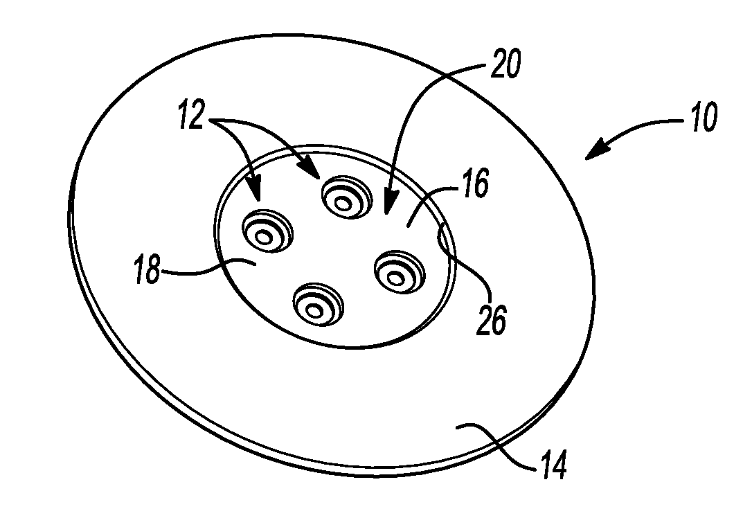
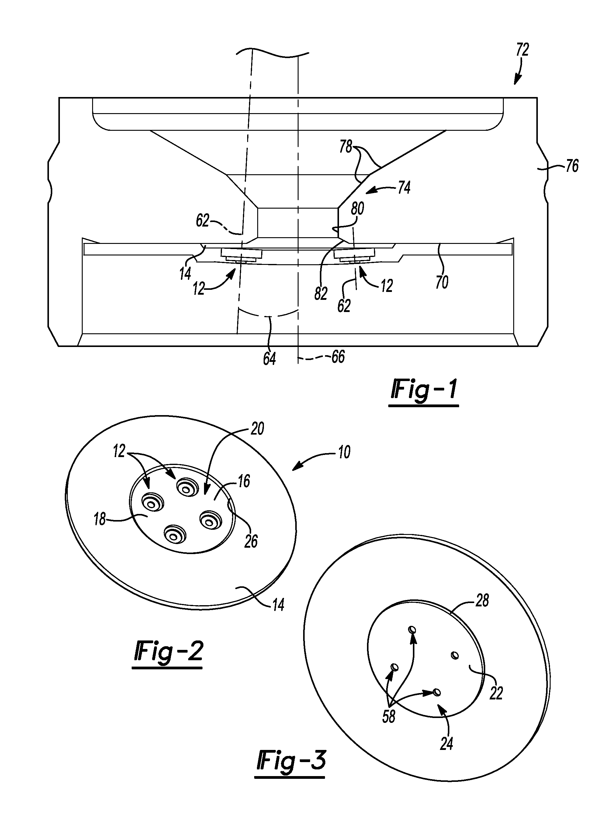
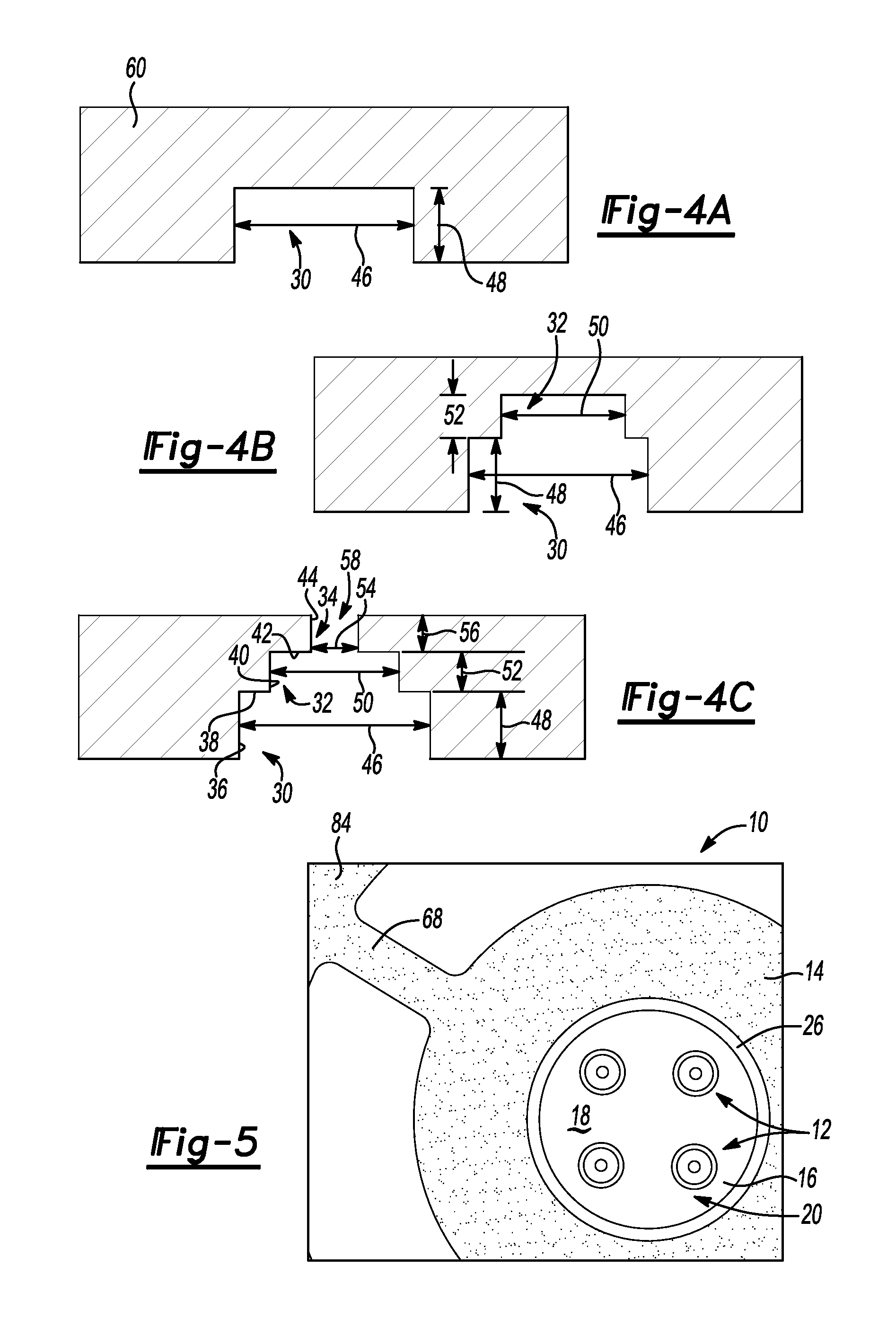
[0024]An orifice plate having a stepped orifice aperture or hole according to embodiments of the present invention is shown in the Figures generally at 10. The plate 10 has at least one, but in some embodiments has a plurality of stepped apertures, shown generally at 12, which allow fluid, such as fuel, to pass through.

[0025]The plate 10 is a single piece part, and has base portion 14 and an offset portion 16. The offset portion 16 forms a recessed surface 18 on the flow entry side, shown generally at 20, and also forms a raised surface 22 on the flow exit side, shown generally at 24. Surrounding the recessed surface 18 is an inner side wall 26 which is substantially parallel to an outer side wall 28, and the outer side wall 28 is adjacent to the raised surface 22. The offset portion 16 is curved or at least partially...


PUM

PropertyMeasurementUnit
Timeaaaaaaaaaa
Angleaaaaaaaaaa
Diameteraaaaaaaaaa

Abstract

An orifice plate used as part of a fuel injector. The orifice plate has a base portion, an offset portion integrally formed with the base portion, a flow entry side and a flow exit side, where the base portion and the offset portion are part of the flow entry side and the flow exit side. A plurality of exit apertures is integrally formed with the offset portion. Each of the plurality of exit apertures includes a plurality of stepped portions, and at least one inner diameter, and each exit aperture is disposed at an angle relative to a central axis extending through the orifice plate. Each exit aperture is of a depth that is about twice the size of the inner diameter, providing optimal atomization of the fluid as the fluid flows through the exit apertures.

Description

FIELD OF THE INVENTION[0001]The invention relates generally to injectors, and more particularly, an orifice disc for a fuel injector which provides sufficient atomization of fuel.BACKGROUND OF THE INVENTION[0002]Injectors are a commonly used device for injecting fuel into the cylinders of an internal combustion engine. One of the ways to improve the efficiency of an engine is to inject the fuel in an “atomized” form. Fuel that is atomized burns much more efficiently, allowing as much of the fuel to be used as possible.[0003]Different fuel injectors are often used with different types of fuel, which have different material properties, and react differently to various temperature changes. One such type of fuel is ethanol, which freezes or solidifies during cold weather conditions. Many attempts have been made to improve the operation of a fuel injector used with ethanol to eliminate freezing of the ethanol.[0004]Spray generation, or atomization, is created by the fluid stream breaking...

Claims


Application Information

Patent Timeline
IPC IPC(8): F02M61/18B05B1/14B26F1/04B05B1/34
CPCF02M61/186F02M2200/8069Y10T29/49996Y10T83/0481F02M61/1833Y10T29/49231F02M61/1806F02M61/1853B05B1/02B05B1/14F02M61/168
Inventor MOSSER, MARK WILLIAMPACYGA, MICHAEL GENE
Owner VITESCO TECH USA LLC
Why Eureka
Try Eureka