Connector having a housing with a first tooth system actuated by a second tooth system on a lever

a technology of electrical connectors and levers, applied in the direction of coupling device connections, coupling parts engagement/disengagement, electrical apparatus, etc., can solve the problem of high insertion force, and achieve the effect of reasonable force and easy installation

Inactive Publication Date: 2015-11-03
DELPHI TECH INC
View PDF15 Cites 12 Cited by
  • Summary
  • Abstract
  • Description
  • Claims
  • Application Information

AI Technical Summary

Benefits of technology

[0006]The object of the invention is to provide a connector system that is easy to install and engage with reasonable force, despite its flat design and large number of contact parts.
[0009]The movement of the connectors towards or away from each other takes place exclusively when the lever moves in the section between the second position and the third position. The movement of the lever between the first and the second positions has no effect on the relative movement of the first and second connectors. The second position of the lever can be designed in such a way that both the insertion forces and the axial movement of the connectors relative to each other meets the requirements. As the location of the first position can be chosen across a wide range, this allows for further reduction of the height of the electrical connector. Thus, very flexible connectors can be designed for difficult installations.
[0013]In another embodiment, the lever has latching arms that serve to hold the lever on the first connector. By securing the lever to the housing, the lever is prevented from moving uncontrollably during assembly.
[0018]In a particularly advantageous embodiment, the material thickness of the rib increases along the extension angle in the first section remains the same in the second section and decreases again in a third section. This ramp shape ensures that the cam is lifted smoothly over the supporting surfaces.

Problems solved by technology

This construction has the disadvantage that the angle which the lever describes when the two connecting connectors are joined is directly related to the distance that the two connecting connectors cover on their way toward each other.
When multi-pin connectors of this kind are assembled, a high insertion force is needed.

Method used


Image

  • Connector having a housing with a first tooth system actuated by a second tooth system on a lever
  • Connector having a housing with a first tooth system actuated by a second tooth system on a lever
  • Connector having a housing with a first tooth system actuated by a second tooth system on a lever

Examples


Embodiment Construction

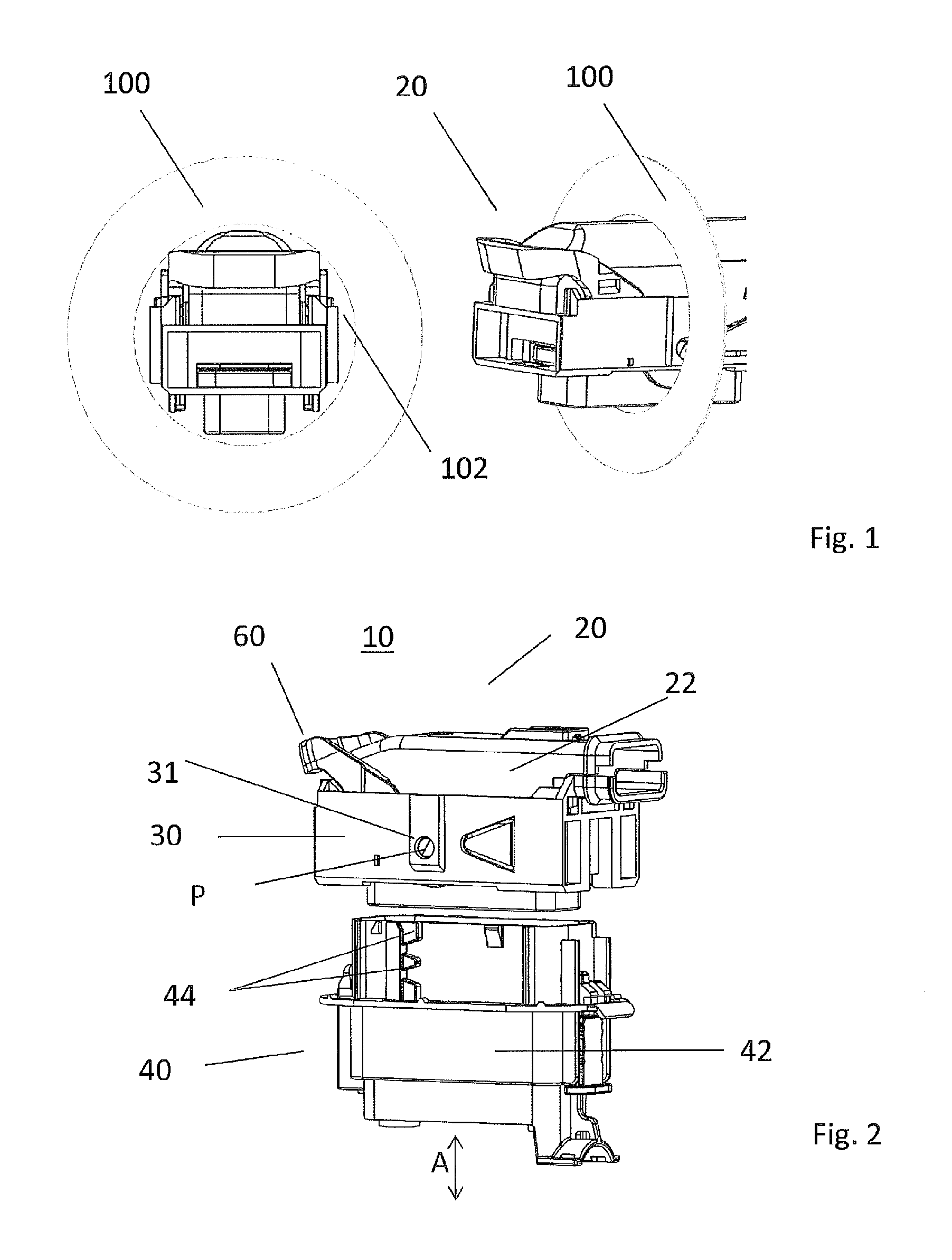
[0036]FIG. 1 shows a first connector 20 which is inserted through an opening 102 in a sheet metal wall 100. It can be seen from this drawing why it is necessary to provide a connector which is flat and in which the lever in the inoperative position lies approximately in the plane of the contact elements and does not protrude from the first connector 20 transversely to the opening 102.

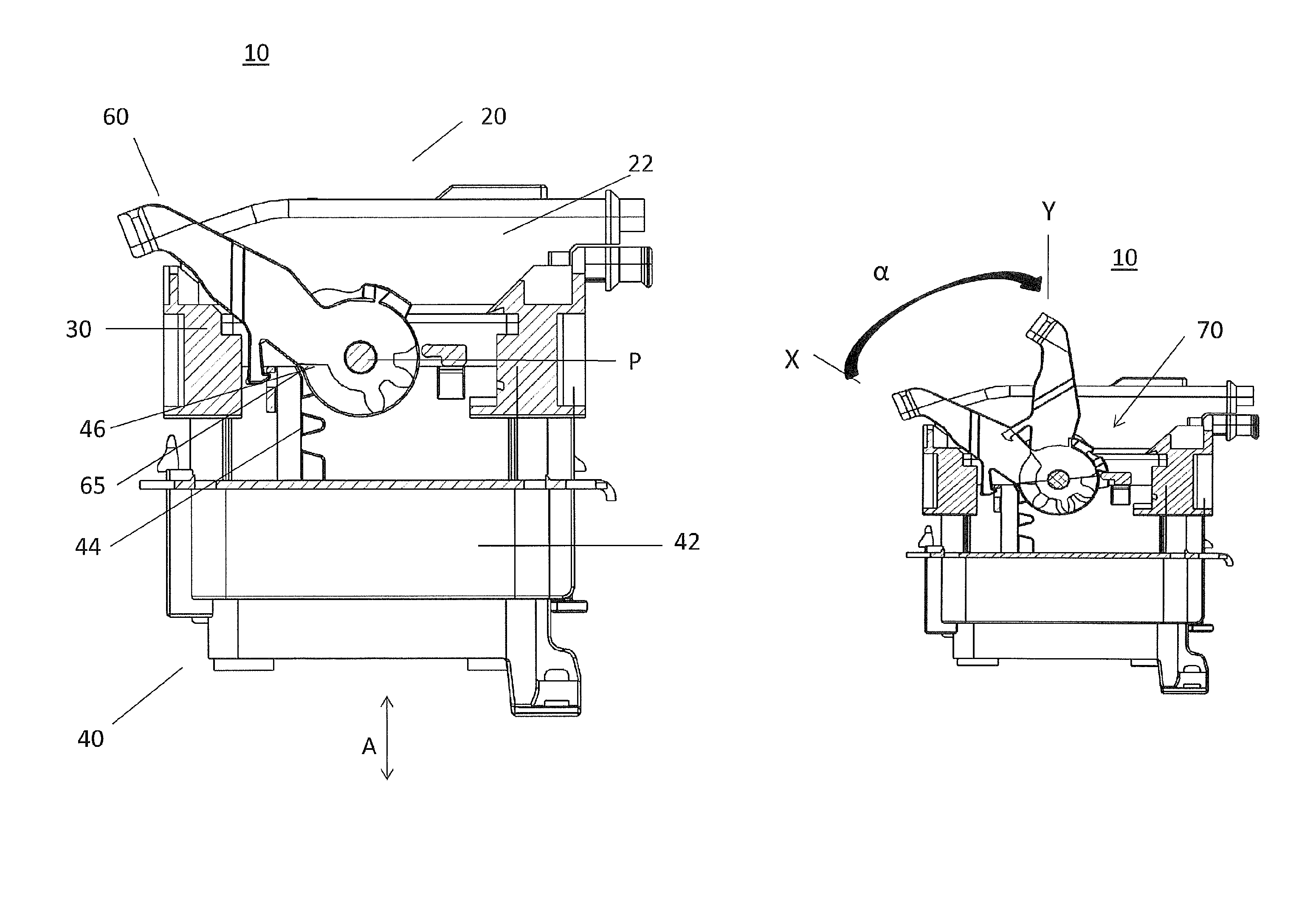
[0037]FIG. 2 shows the connector system 10 according to the invention. The first connector 20 comprises a first housing 22, the lever 60 and the frame 30; the lever 60 is mounted pivotally around pivot point P. The second connector 40 comprises a second housing 42 that has a first tooth system 44 on its surface.

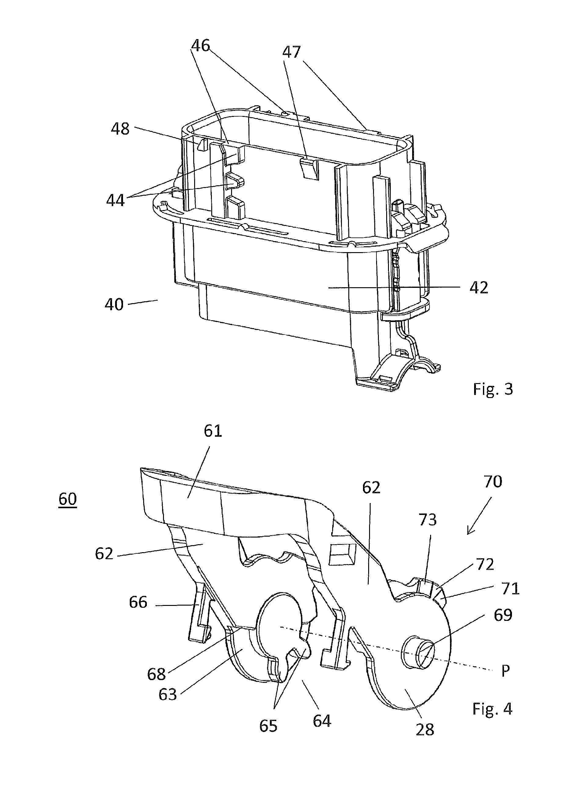
[0038]FIG. 3 shows a perspective view of the second connector 40. The upper area shows two supporting areas, 46 and 47, on which, when fitted together, the first connector 20 rests during the connecting process. The supporting areas 46 are provided for the lever 60, and the supporting areas 47 ar...


PUM


Abstract

A connector system having a first connector and a second connector. The first and the second connector are moveable relative to one another along an axis in order to connect and disconnect the contacts of the first connector and the second connector. The first connector has a lever mounted at the pivot point and is pivotal around an angle. The lever has a surface extending in the circumferential direction and which extends substantially through the essentially along the same angle. The surface has a first planar section and a second section having a radially extending tooth system. The lever is movable from a first, second, and third position. The housing of the second connector has a complementary tooth system. The tooth systems become engaged when the lever is moved from the second to third position, thus moving the first connector and the second connector toward one another along the axis.

Description

CROSS-REFERENCE TO RELATED APPLICATION[0001]This application is a national stage application under 35 U.S.C. §371 of PCT Application Number PCT / EP2012 / 071139 having an international filing date of Oct. 26, 2012, which designated the United States, which PCT application claimed the benefit of Great Britain Patent Application Number 1118499.1, filed Oct. 26, 2011, the entire disclosure of each of which are hereby incorporated herein by reference.TECHNICAL FIELD OF THE INVENTION[0002]The present invention relates to a two-part electrical connector, which can be connected or disconnected by means of a lever.BACKGROUND OF THE INVENTION[0003]In the prior art, various embodiments of connectors are known. A connector can have two housings with contacts, which can be pulled together from a pre-assembly position into a final position by means of a lever arm pivotally mounted onto a housing. In doing so, the lever arm forms a bow relative to the housing. The lever arm comprises a surface from ...

Claims


Application Information

Patent Timeline
Patent Type & Authority Patents(United States)
IPC IPC(8): H01R13/62H01R13/533H01R13/629H01R13/627
CPCH01R13/62977H01R13/533H01R13/62938H01R13/62944H01R13/6271H01R13/6295
Inventor PAPURCU, NECDETSCHATTLING, JOERGWEIDEMEYER, ANDREAS
Owner DELPHI TECH INC
Why Eureka
Try Eureka