Method and device for ultrasound processing of a material web

a technology of ultrasound processing and material web, which is applied in the direction of layered products, chemistry apparatus and processes, and other domestic articles, can solve the problems of inaccurate relative positioning of sonotrodes and anvils in this device, complicating the use of devices, and affecting the accuracy of ultrasound processing, so as to increase the accuracy of adjustment of minimum separation, the effect of accurate adjustmen

Active Publication Date: 2009-01-29
TEXTI SONICS SAS
View PDF6 Cites 12 Cited by
  • Summary
  • Abstract
  • Description
  • Claims
  • Application Information

AI Technical Summary

Benefits of technology

[0042]Such a structure is simple, reliable and robust.
[0043]Said one connecting portion is preferably the first connecting portion on the first body part and said other connecting portion is preferably the second connecting part on the second body part. As a result, during adjustment, the user operates on members carried by the fixed part of the device, which guarantees a more accurate adjustment.
[0044]The first and second device body parts are preferably rotationally articulated to each other about a transverse axis close to the working area, whereas the connecting portions on the first and second device body parts, which receive the manually adjustable mechanical means, are on the opposite side of the transverse axis to the working area and are remote from the transverse axis, in the vicinity of the distal part of the ultrasound converter. This therefore increases very significantly the accuracy of adjustment of the minimum separation, where accuracy is necessary to adapt to the generally small thicknesses of thermofusible fabrics and to guarantee more regular welding.
[0045]The compression spring or springs may advantageously be positioned at substantially the same distance from the transverse axis as the abutment means for limiting convergent movement, in order to improve further the accuracy of adjustment.
[0046]To improve the accuracy of adjustment still further, the compression spring may preferably be engaged around the tie-rod.

Problems solved by technology

This makes the relative positioning of the sonotrode and the anvil inaccurate.
Because of the large distance between the rotation axis and the working area, the relative positioning of the sonotrode and the anvil is inaccurate in this device.
The adjustments of the bearing force and the relative position between the sonotrode and the anvil are interdependent, which complicates the use of the device and degrades the accuracy and the reproducibility of the adjustments.
In all cases, the ultrasonic vibrations of the sonotrode cause total or partial melting of the part of the material disposed between the sonotrode and the anvil.
Usually insufficient melting is found, and therefore insufficient welding, with the risk of the textile material fraying after cutting.
Conversely, excessive melting of the material is often noted, which causes plasticization of the welded areas, making them stiffer and more fragile, introducing a risk of subsequent tearing of the textile material.
It is therefore very difficult to control the result obtained.
Furthermore, premature wear of the anvils and the sonotrodes is regularly observed, which necessitates maintenance operations to change these parts, failing which the result obtained becomes even more random.
Also known are more complex devices in which the sonotrode is moved relative to the anvil by hydraulic or pneumatic means, with sensors for monitoring the result obtained and controlling the relative displacement of the sonotrode with respect to the anvil.
Such a machine is very complex and costly, however, and necessitates a source of pneumatic or hydraulic energy, which renders it inapplicable under many conditions of use, for example at the exit from circular weaving looms.

Method used


Image

  • Method and device for ultrasound processing of a material web
  • Method and device for ultrasound processing of a material web
  • Method and device for ultrasound processing of a material web

Examples


Embodiment Construction

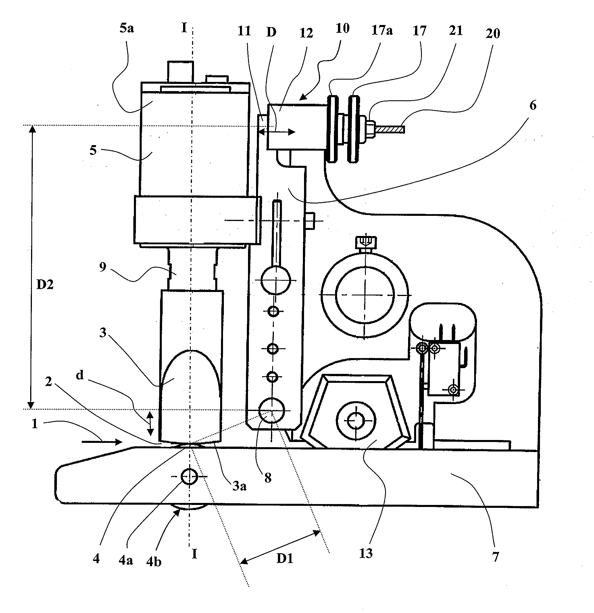
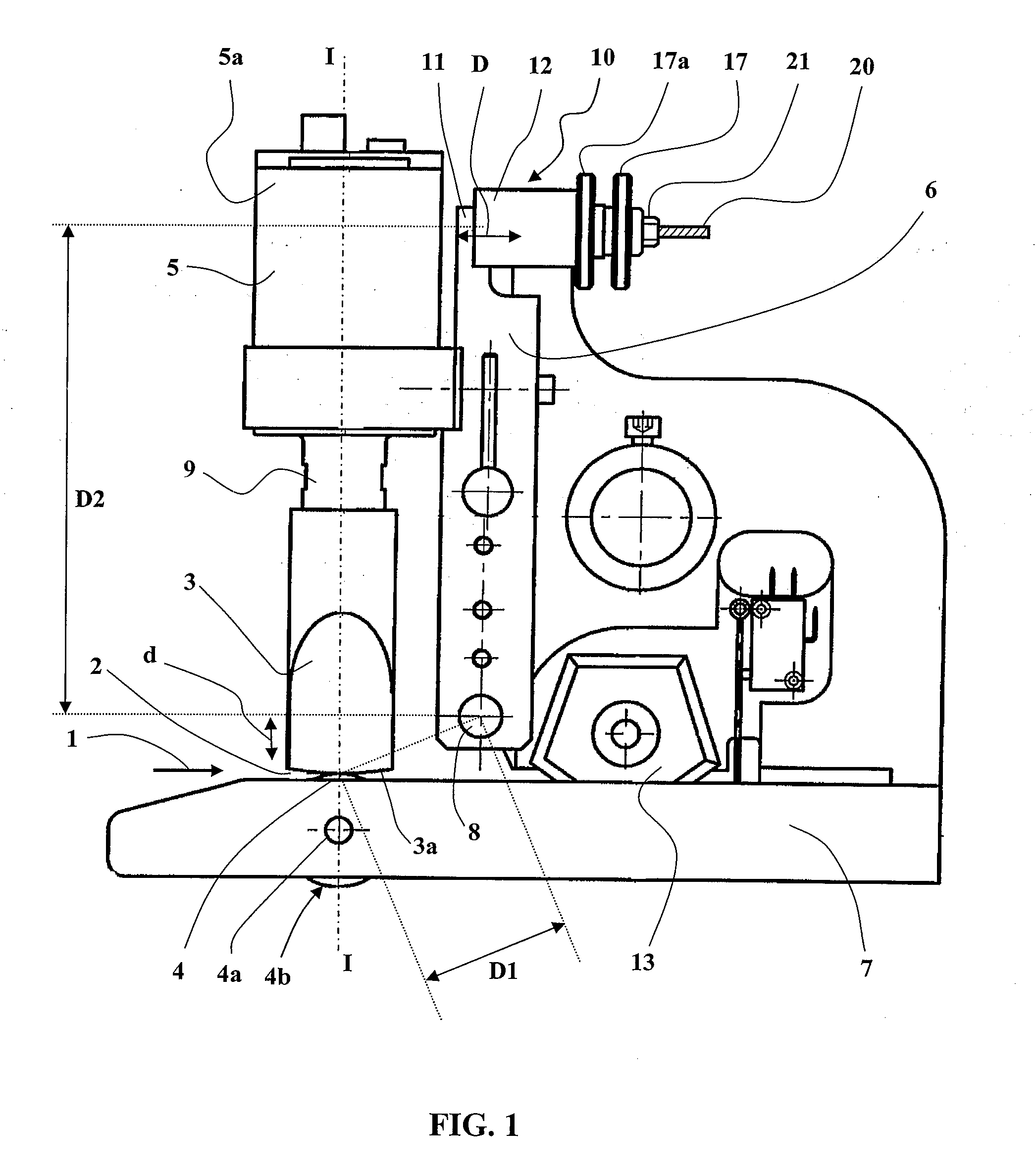
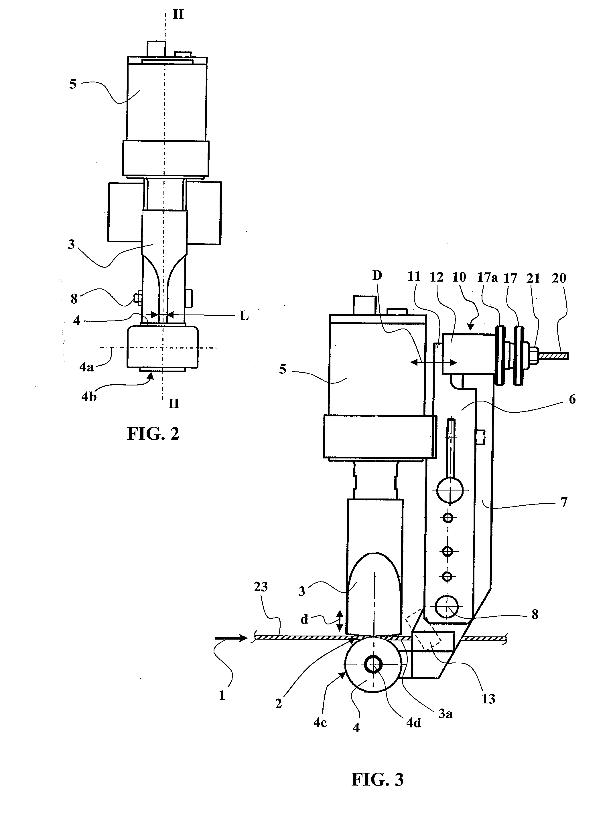
[0093]FIGS. 1 to 6 show, by way of illustrative but nonlimiting example, three embodiments of a device in accordance with the present invention for ultrasound processing of strips of material.

[0094]The device from FIGS. 1 and 2 is a continuous ultrasound spot welding machine with integrated mechanical cutting which produces two lateral spot welds over a width of several millimeters followed by a mechanical cut in the median area between the welds.

[0095]The device from FIGS. 3 and 4 is a continuous ultrasound cutting and welding machine which produces a welding cut with two continuous welds each over a width of approximately 1 mm on either side of the cutting line.

[0096]The device from FIGS. 5 and 6 is another continuous ultrasound cutting and welding device.

[0097]In each of the three embodiments, most of the structural elements recur, and the corresponding elements are identified by the same numerical references.

[0098]In each case, the device is in principle intended to process a st...


PUM

PropertyMeasurementUnit
widthaaaaaaaaaa
widthaaaaaaaaaa
widthaaaaaaaaaa

Abstract

A sonotrode and an anvil have a spacing determined by a manually adjustable mechanical device. The adjustable mechanical device includes an abutment device which maintains the distance between the sonotrode and the anvil greater than the minimum space, and which is provided with an elastic device for elastically attracting the sonotrode and the anvil to each other. Thus, it is possible to control efficiently the melting of material between the sonotrode and the anvil, for reliable welding, or for efficient cutting, or for welding along the cutting line.

Description

TECHNICAL FIELD OF THE INVENTION[0001]The present invention concerns methods and manually adjustable devices for ultrasound processing of a strip or a web of material, in particular textile material strips or webs based on thermofusible materials.[0002]Ultrasound is routinely used to process thermofusible materials, for example to effect cutting, welding, lamination.[0003]A machine for this requiring manual adjustment is already known. This machine generally comprises a sonotrode, functionally associated with an ultrasound converter that applies to it a vibration at ultrasound frequency. The sonotrode is held opposite an anvil on respective opposite sides of a working area into which the material to be processed is introduced. The sonotrode is carried by a first device body part and the anvil is held by a second device body part. The first and second device body parts are articulated to each other about a transverse axis to modify the distance between the sonotrode and the anvil by ...

Claims


Application Information

Patent Timeline
Patent Type & Authority Applications(United States)
IPC IPC(8): B32B37/00B29C65/00B29C65/08B29C65/74
CPCB29C65/086Y10T156/1054B29C65/7435B29C65/7443B29C65/745B29C66/80B29C66/81419B29C66/81422B29C66/8169B29C66/8242B29C66/83411B29C66/84B29C66/861B29C66/9241B29C66/92611B29K2313/00B29L2031/3067B29C65/74Y10T156/1084Y10T156/1378B29C66/729B29C66/81417B29C66/92653B29C65/00B29C66/43B29C66/8161B29C66/8221B29C66/8223B29C65/7459B29C66/7352B29C66/1122B29C66/0062B29C66/876
Inventor ABATE, PIETRO
Owner TEXTI SONICS SAS
Why Eureka
Try Eureka