Rear projection display apparatus

a rear projection display and display device technology, applied in the direction of projectors, color television details, instruments, etc., can solve the problems of low generation of distortion after mounting (assemblage), difficult to change the installation site easily, increase the weight of the main body part, etc., to achieve enhanced stiffness, reduce material thickness, and high accuracy

Inactive Publication Date: 2007-08-02
SONY CORP
View PDF3 Cites 13 Cited by
  • Summary
  • Abstract
  • Description
  • Claims
  • Application Information

AI Technical Summary

Benefits of technology

[0015] According to the rear projection display apparatus in the present invention configured as above, the skeleton of the structure body includes the frame body including the bottom frame, the left and right side frame and the top frame, and the frame support for supporting the left and right side frames of the frame body, for example from a skew direction in a bracing manner. Besides, the frames are each composed of an extruded member with a uniform section, high accuracy and in a predetermined shape according to the location of use thereof, and the hardening of the material by the extrusion promises a reduction in material thickness and an enhanced stiffness. In addition, the skeleton of the structure body can be strengthened by the frame support.
[0016] According to the rear projection display apparatus in the present invention, the skeleton of the structure body can be configured to be high in accuracy and sufficient in rigidity, while using a reduced number of members.

Problems solved by technology

Therefore, it may be necessary to provide the main body part 102 with sufficient rigidity, and the reinforced structure would cause an increase in the weight of the main body part 102 itself, making it difficult to change easily the installation site of the rear projection display apparatus.
Therefore, though the possibility of generation of distortion after mounting (assemblage) is low, the weight of the frame itself would be large.

Method used


Image

  • Rear projection display apparatus
  • Rear projection display apparatus
  • Rear projection display apparatus

Examples


Embodiment Construction

[0043] Now, an embodiment of the present invention will be described below referring to FIGS. 1 to 23.

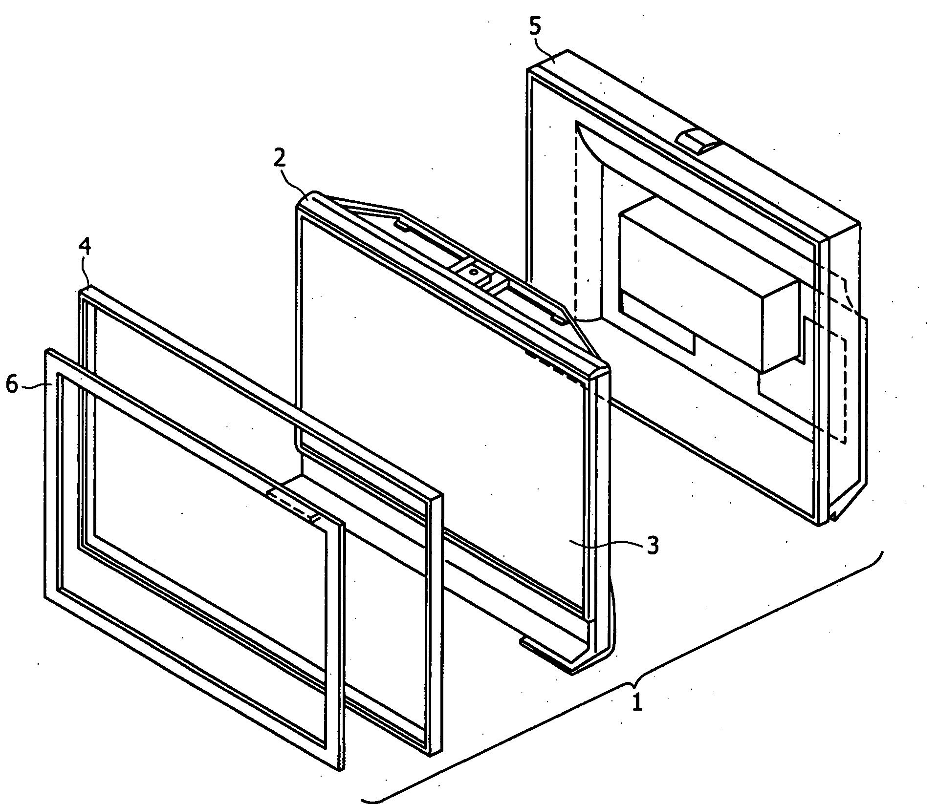
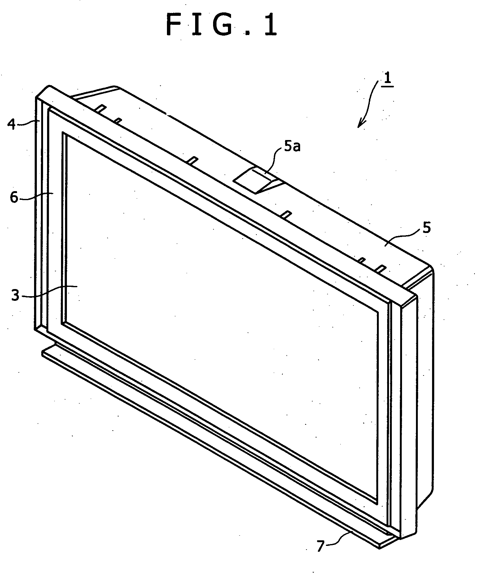
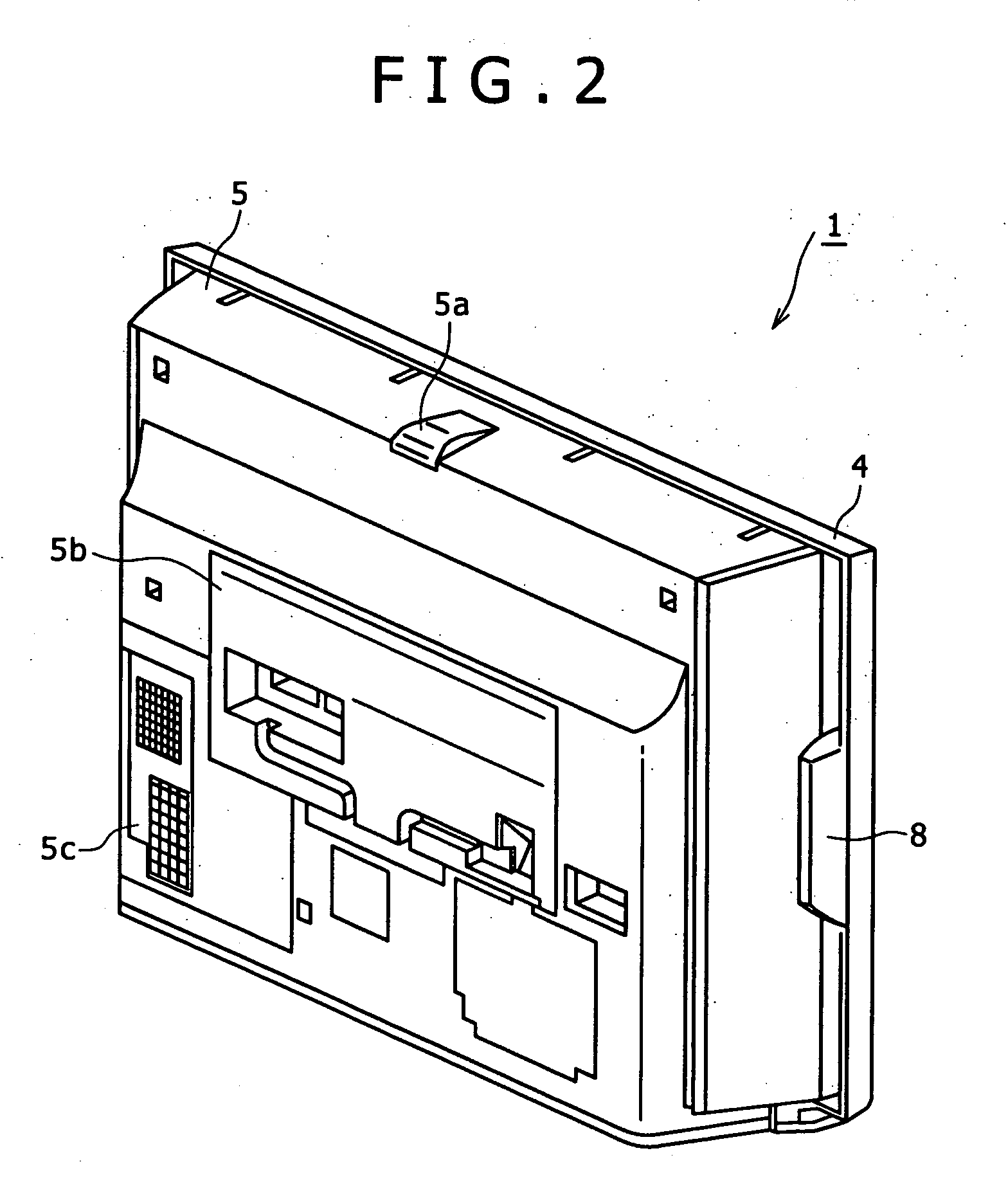
[0044]FIG. 1 is a perspective view, from the front side, of a rear projection display apparatus according to the present embodiment, and FIG. 2 is a perspective view, from the rear side, of the rear projection display apparatus. Besides, FIG. 3 is an exploded perspective view showing a general configuration of the rear projection display apparatus.

[0045] In this embodiment, the video display screen of the rear projection display apparatus is, for example, of the 50-inch type, and the front-rear dimension (thickness) of the display is as small as 30 cm, for example.

[0046] Numeral 1 in FIGS. 1 to 3 denotes the rear projection display apparatus. As shown in FIG. 3, the rear projection display apparatus 1 has a configuration in which, to a display unit 2 provided with a screen 3 of the rear projection type at its front side, an outer frame 4 and a cover frame 6 are mounted from the f...


PUM


Abstract

Disclosed herein is a rear projection display apparatus including, a screen, a projection mirror, a video apparatus for projecting a picture, an optical unit including a projection lens, a light source, a drive and control circuit, and a structure body for holding the screen, the structure body having, a frame body formed from an extruded metal member, and a reinforcement member formed from a sheet metal, the frame body including, a bottom frame constituting a bottom surface, left and right side frames erected at both ends on the front side of the structure body, of the bottom frame, and a top frame bridgingly disposed between the upper ends of the left and right side frames, and the reinforcement member including, at least a frame support for connecting between the bottom surface of the bottom frame and the right side frame, or connecting between the bottom surface of the bottom frame and the left side frame.

Description

CROSS REFERENCES TO RELATED APPLICATIONS [0001] The present invention contains subject matter related to Japanese Patent Application JP 2005-380625 filed in the Japanese Patent Office on Dec. 29, 2005, the entire contents of which being incorporated herein by reference. BACKGROUND OF THE INVENTION [0002] 1. Field of the Invention [0003] The present invention relates to a rear projection display apparatus such that a video apparatus, an optical unit including a projection lens, a light source, a mirror and the like are provided therein and a screen is attached to the front side thereof. [0004] 2. Description of the Related Art [0005]FIG. 24 shows an example of the internal configuration of a rear projection display apparatus in the related art. This rear projection display apparatus is so configured that an image from a projected image forming part in a projector main body 100 disposed at a rear lower position inside a casing is projected by a projection lens while being projected ba...

Claims


Application Information

Patent Timeline
Patent Type & Authority Applications(United States)
IPC IPC(8): H04N9/12
CPCG03B21/10G03B21/56G03B21/28G03B21/14G03B21/145G03B21/00
Inventor HIRAMATSU, YOICHI
Owner SONY CORP
Why Eureka
Try Eureka