
Seamless instrument panel passenger air bag door

Active Publication Date: 2016-03-17
FORD GLOBAL TECH LLC
View PDF3 Cites 16 Cited by
  • Summary
  • Abstract
  • Description
  • Claims
  • Application Information

AI Technical Summary

Benefits of technology

The patent describes an air bag housing with a cover that has a tear seam. The cover has three segments and a hinge area. The technical effect is to create a secure and reliable air bag housing that can protect the air bag from damage during deployment.

Problems solved by technology

However, air bags incorporated into instrument panels of certain designs may make deflection or other interference with a deploying air bag desirable.

Method used


Image

  • Seamless instrument panel passenger air bag door
  • Seamless instrument panel passenger air bag door
  • Seamless instrument panel passenger air bag door

Examples


Embodiment Construction

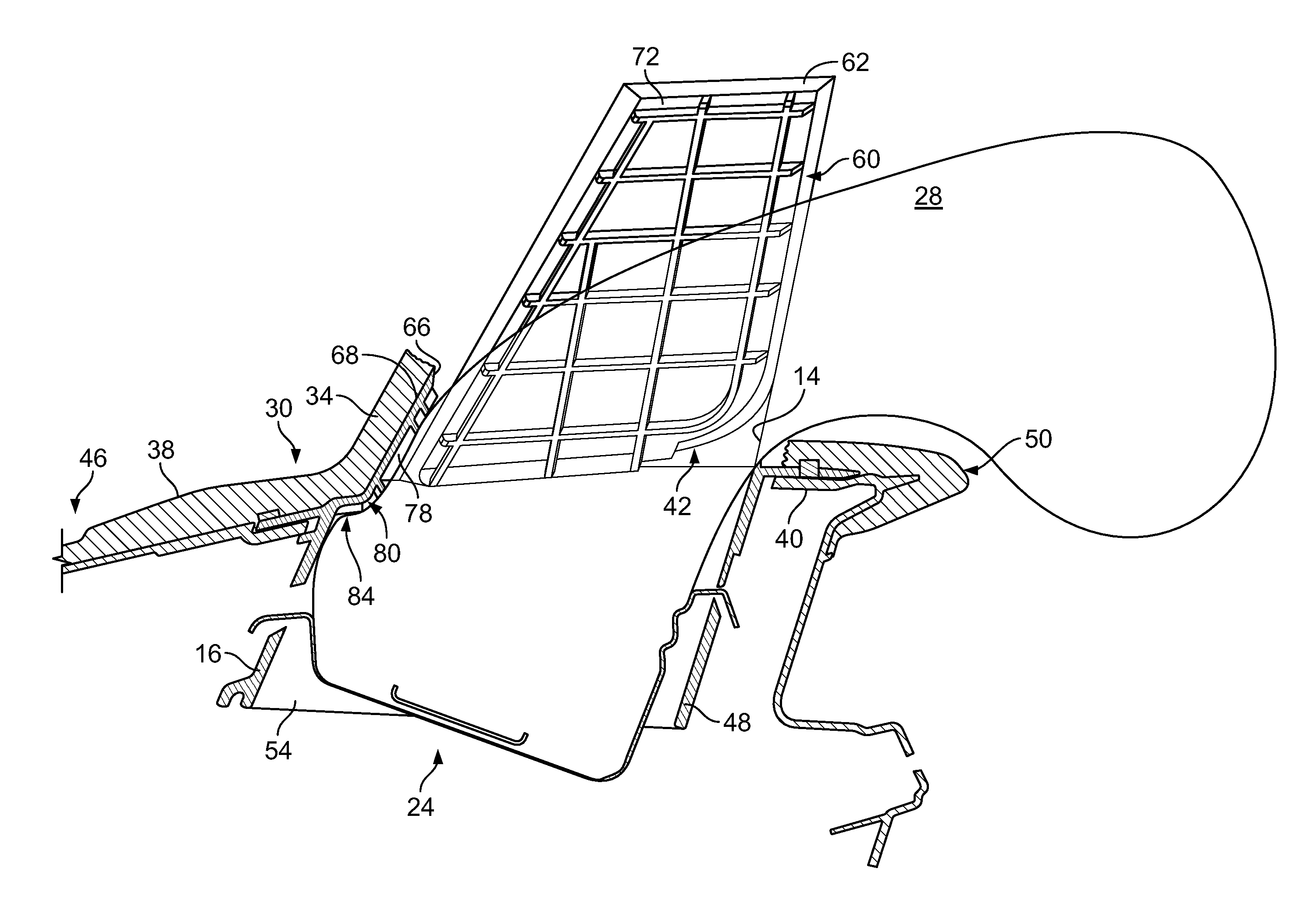
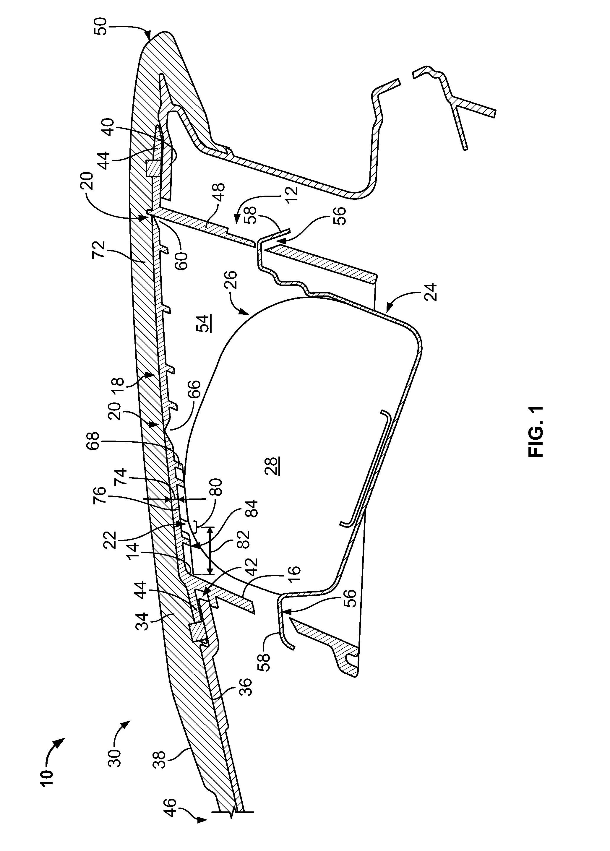
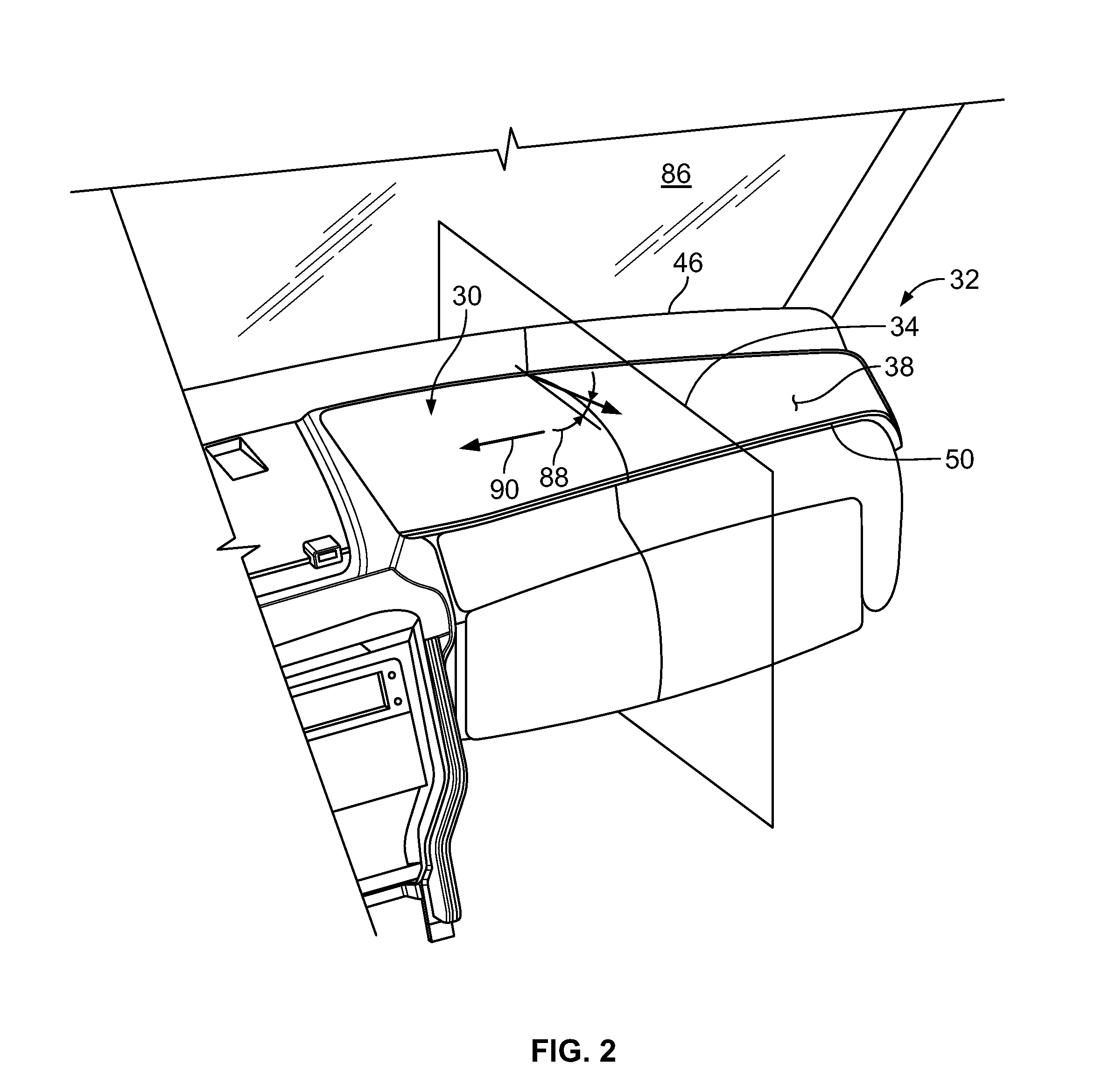
[0015]For purposes of description herein, the terms “upper,”“lower,”“right,”“left,”“rear,”“front,”“vertical,”“horizontal,”“interior,”“exterior,” and derivatives thereof shall relate to the invention as oriented in FIG. 1. However, it is to be understood that the invention may assume various alternative orientations, except where expressly specified to the contrary. It is also to be understood that the specific devices and processes illustrated in the attached drawing, and described in the following specification are simply exemplary embodiments of the inventive concepts defined in the appended claims. Hence, specific dimensions and other physical characteristics relating to the embodiments disclosed herein are not to be considered as limiting, unless the claims expressly state otherwise. Additionally, unless otherwise specified, it is to be understood that discussion of a particular feature of component extending in or along a given direction or the like does not mean that the featu...


PUM


Abstract

An air bag housing includes a chute defining an upper perimeter with a first wall extending from the upper perimeter and a cover extending over the chute integrally from the upper edge. The cover defines a tear seam extending between opposite portions of the upper perimeter remote from the first wall and a hinge area extending between the opposite portions of the upper perimeter and disposed between the first wall and the tear seam.

Description

FIELD OF THE INVENTION[0001]The present invention generally relates to an air bag housing structure. Specifically, the housing structure includes features for controlled deflection of an air bag during deployment therefrom.BACKGROUND OF THE INVENTION[0002]Automotive air bag systems include an air bag module mounted within a housing that is concealed beneath a surface of the vehicle interior. In particular, passenger air bag systems may include a chute defined by the housing and extending within the instrument panel of the associated vehicle. The chute may be concealed beneath a surface of the instrument panel, or outer substrate thereof. In such an arrangement, the outermost layer of the instrument panel extends over an opening to the air bag chute and is supported by a door panel that is movably coupled with a portion of the housing, which may include a wall of the chute. The adjacent portion of the instrument panel or outer substrate thereof includes a pre-weakened tear line that ...

Claims


Application Information

Patent Timeline
IPC IPC(8): B60R21/2165B60R21/205
CPCB60R21/205B60R21/2165B60R2021/21537
Inventor KWASNIK, KENNETH J.TREVINO, LISANDROWEST, SEAN BAYLE
Owner FORD GLOBAL TECH LLC
Learn More