Switching booster power circuit

a power circuit and booster technology, applied in the direction of pulse automatic control, power conversion system, dc-dc conversion, etc., can solve the problems of high cost of switching element, delay in switching control control, damage of switching element, etc., and achieve the effect of easily and stably controlling the switching elemen

Inactive Publication Date: 2009-12-29
DENSO CORP
View PDF10 Cites 1 Cited by
  • Summary
  • Abstract
  • Description
  • Claims
  • Application Information

AI Technical Summary

Benefits of technology

[0017]Accordingly, rush current is restricted from passing through the switching element, and the switching element can be easily and stably controlled.

Problems solved by technology

In this case, the transistor may be damaged.
However, when the switching element has the relatively large capacity to withstand the rush current, the switching element may be expensive.
In this case, the starting of the controlling of the switching control may be too much delayed even after the rush current passes through the circuit.
Then, start of voltage increasing by the booster circuit may be delayed.
Therefore, time is more needed for activating the microcomputer, so that the start of the voltage increasing by the booster circuit may be much delayed.
Because voltage supplied from the direct-current power source is not directly used as the reference voltage for the switching control to start controlling the switching element, the start of the controlling of the switching element may be more delayed.
Thus, the start of the controlling of the switching element may be more delayed.
That is, in the case where the microcomputer controls the switching control, the start of the controlling of the switching element may be too much delayed.

Method used


Image

  • Switching booster power circuit
  • Switching booster power circuit
  • Switching booster power circuit

Examples


Embodiment Construction

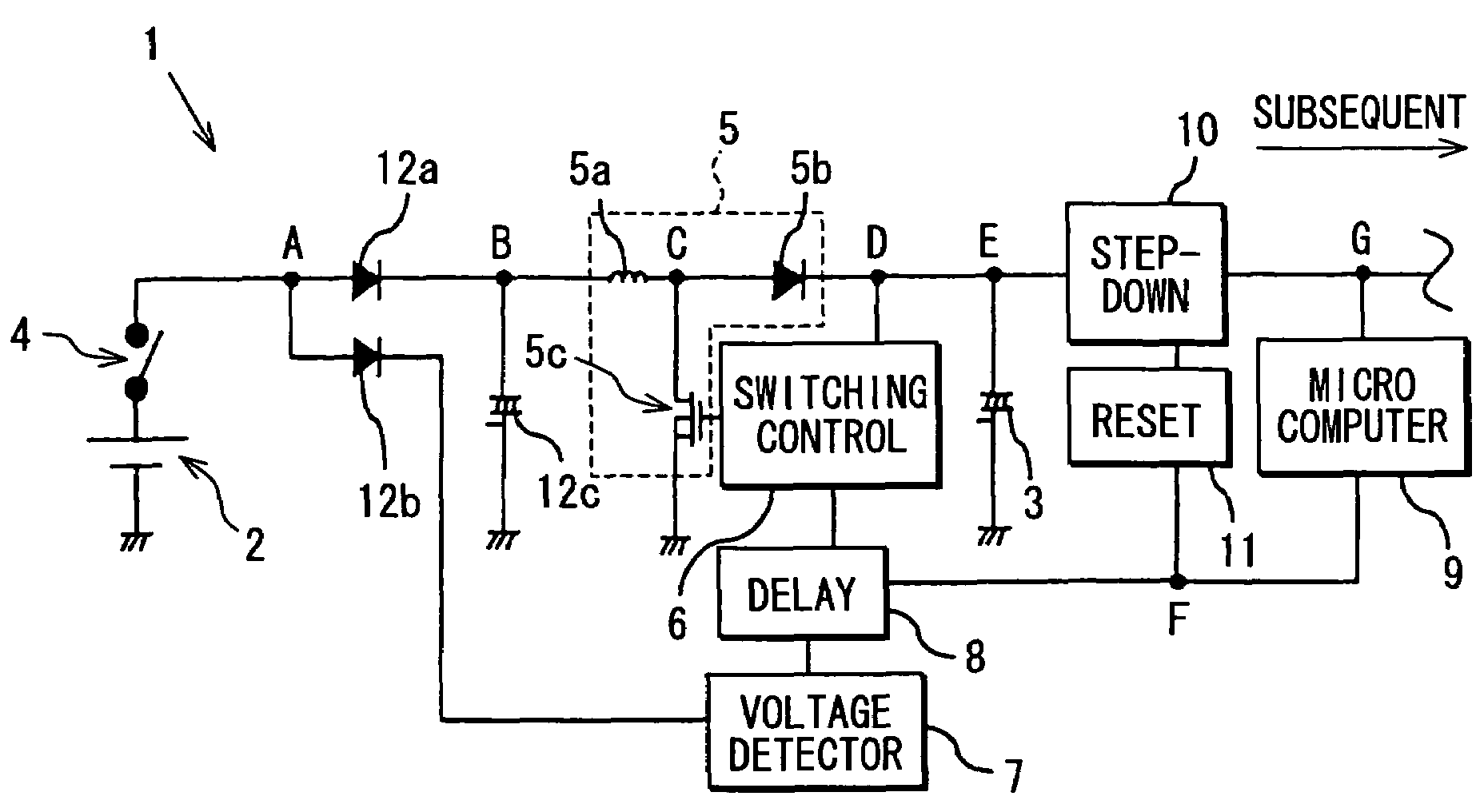
[0023]As shown in FIG. 1, a switching booster power circuit 1 includes a power switch 4, a booster (voltage step-up) circuit 5, a switching control 6, a voltage detector 7, a delay circuit 8, a microcomputer 9, a voltage step-down circuit 10 and a reset circuit 11. The power switch 4 connects a battery 2 (direct-current power source) and an output capacitor 3 (electric load). Further, the switching booster power circuit 1 includes a diode 12a, a diode 12b and a smoothing capacitor 12c, which are used for stabilizing voltage of the battery 2.

[0024]A positive electrode of the battery 2 is connected to the power switch 4, and a negative electrode of the battery 2 is connected to a vehicle ground (GND). When the power switch 4 is turned on, the battery 2 supplies electricity to the output capacitor 3. Here, a line from the power switch 4 to the output capacitor 3 is defined as an electricity supply line. Immediately after the power switch 4 is turned on, an equivalent impedance of the o...


PUM


Abstract

A switching booster power circuit includes a power switch, a booster circuit, a switching control, a voltage detector and a delay circuit. The voltage detector detects an input voltage value at a predetermined point of an electricity supply line from the power switch to an electric load, and determines the input voltage value to be larger than a predetermined voltage threshold or not. The delay circuit outputs an enabling signal enabling the switching control to operate, when a predetermined time period is elapsed after the input voltage value becomes larger than the voltage threshold.

Description

CROSS REFERENCE TO RELATED APPLICATION[0001]This application is based on Japanese Patent Application No. 2006-303860 filed on Nov. 9, 2006, the disclosure of which is incorporated herein by reference in its entirety.BACKGROUND OF THE INVENTION[0002]1. Field of the Invention[0003]The present invention relates to a switching booster power circuit.[0004]2. Description of Related Art[0005]A switching booster (step-up) power circuit includes a booster circuit and a switching control between a direct-current power source and a capacitor. The booster circuit has a switching element, and the switching control controls on / off of the switching element of the booster circuit.[0006]JP-A-7-123708 discloses a booster circuit, which is constructed by a coil, a diode and a switching element, e.g., transistor, for example. The booster circuit gradually increases voltage, so that the capacitor of the switching booster power circuit can be charged with a larger amount of energy.[0007]That is, the swit...

Claims


Application Information

Patent Timeline
Patent Type & Authority Patents(United States)
IPC IPC(8): H02M3/18G05F1/40
CPCH02M3/156H02M1/36
Inventor ITO, MASAHIKO
Owner DENSO CORP
Why Eureka
Try Eureka