Inflatable flat winding chuck

An inflatable collet technology, applied in the field of inflatable flat rewinding collets, can solve the problems of large axial size, high cost, and large space occupation of the rewinding collet, and achieve stable airway control Convenience, guaranteed stability, stable effect

Inactive Publication Date: 2021-06-08
浙江华创机电科技有限公司
View PDF6 Cites 0 Cited by
  • Summary
  • Abstract
  • Description
  • Claims
  • Application Information

AI Technical Summary

Problems solved by technology

Its disadvantages are: the axial dimension of the winding chuck is relatively large, and the space occupied in the actual layout is relatively large, and the cost is too high when it is applied to the winding of narrow-width materials

Method used


Image

  • Inflatable flat winding chuck
  • Inflatable flat winding chuck
  • Inflatable flat winding chuck

Examples


Embodiment 1

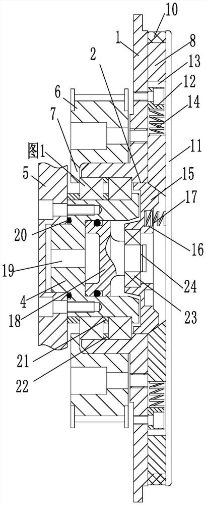
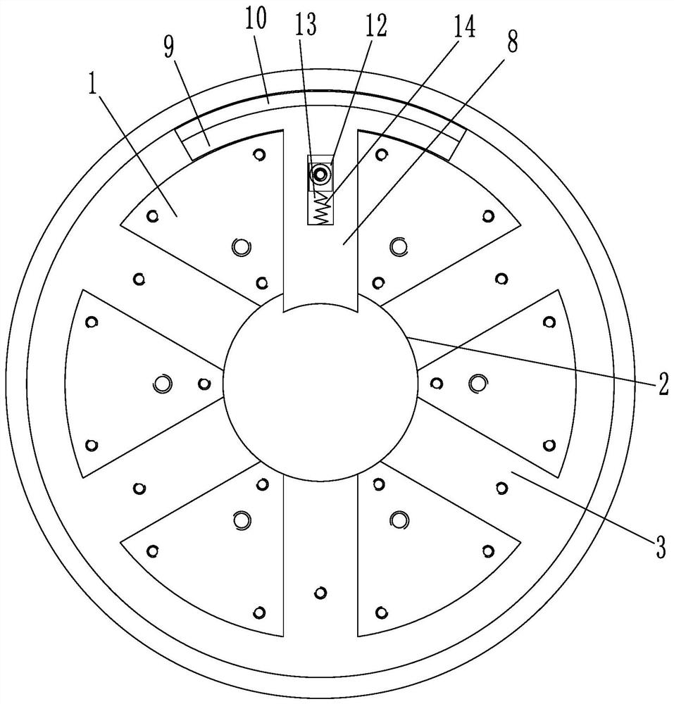
[0024] figure 1 and figure 2Among them, an inflatable flat rewinding collet is characterized in that it includes a collet body 1, the collet body 1 is a stepped shaft structure composed of two coaxial cylinders, and the two parts of the collet body 1 are arranged according to the diameter. The section cylinder is divided into a large shaft and a small shaft. One side of the chuck main body 1 is rotated to be provided with an end shaft 4 , and the inside of the chuck main body 1 is provided with a cylindrical hole for installing the end shaft 4 . The end shaft 4 is threadedly connected with a winding driving arm 5, the end shaft 4 is connected with the chuck main body 1 through a pair of bearings, and the cylindrical hole and the bearing are interference fit. A fixed-distance inner ring 21 and a fixed-distance outer ring 22 are arranged between the paired bearings. The fixed-distance inner ring 21 is interference-fitted on the end shaft 4, and the outer side of the fixed-dis...

Embodiment 2

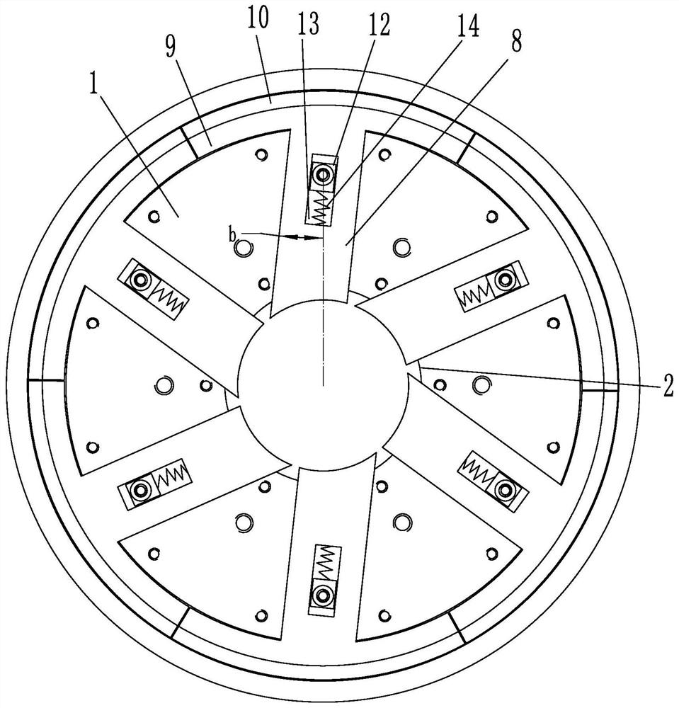
[0026] An inflatable flat rewind chuck, such as image 3 As shown, the difference between Embodiment 2 and Embodiment 1 is that the straight line where the limit block 12 and the chute 13 are located is set radially obliquely to the collet body 1 where the limit block 12 is located, and the position where the limit block 12 and the chute 13 are located The included angle b between the straight line and the radial inclination of the collet body 1 where the limit block 12 is located can be selected within the range of 5 to 8 degrees, and the embodiment adopts 6.15 degrees. Sliding groove 3 and chute 13 are parallel. The collet expansion block 8 is arranged obliquely with the sliding groove 3, and a certain inclination angle is formed between the collet expansion block 8 and the chuck main body 1. The pressure of the block 8 is partly borne by the chuck main body 1 through the inclination angle, which reduces the matching pressure between the inner end of the chuck expansion blo...


PUM


Abstract

The invention discloses an inflatable flat winding chuck which comprises a chuck body, an end shaft is rotatably arranged on one side of the chuck body, a plurality of chuck expansion blocks are slidably arranged on the side, back to the end shaft, of the chuck body, sliding grooves matched with the chuck expansion blocks are formed in the chuck body, and the outer ends of the chuck expansion blocks can stretch out of the sliding grooves; a chuck cover plate is arranged at the ends, back to the chuck body, of the chuck expansion blocks, limiting blocks are arranged on the chuck body, sliding grooves matched with the limiting blocks are formed in the chuck expansion blocks, and first reset pieces matched with the limiting blocks are arranged in the sliding grooves; conical shafts are arranged between the chuck expansion blocks and the end shaft, and second reset pieces are arranged between the conical shafts and the chuck cover plate; the end surfaces of the conical shafts are matched with the chuck expansion blocks, and a synchronous belt wheel is arranged outside the chuck body; and a piston is arranged in the end shaft and rotationally connected with the conical shafts, and an air inlet channel matched with the piston is arranged in the end shaft. The inflatable flat winding chuck has the advantages that the inflatable flat winding chuck can be applied to winding of narrow materials and can reduce the narrow material winding cost while meeting the large opening diameter.

Description

technical field [0001] The present application relates to the technical field of winding chucks, in particular to an inflatable flat winding chuck. Background technique [0002] Winding is the receiving part of the processing production line. The raw materials are mechanically wound into rolls. It is widely used in paper rolls, cloth rolls, plastic rolls, metal coils and other processing production lines. , roll outer diameter, roll material thickness and width, etc. have strict requirements. When winding and unwinding the coil, the air-expanding chuck is usually used. After inflation, the surface protrusions press the inner surface of the coil, and the protrusions on the deflated surface retract to loosen the inner surface of the coil. It needs to be kept during application. Gas pressure is needed to complete the surface compaction of the coiled material. The air expansion chuck in the prior art has the problem of large volume and large width of the chuck, and the cost is ...

Claims


Application Information

Patent Timeline
Patent Type & Authority Applications(China)
IPC IPC(8): B65H75/24
CPCB65H75/248
Inventor 许炯
Owner 浙江华创机电科技有限公司
Why Eureka
Try Eureka