
Continuously variable transmission

a transmission and variable technology, applied in the direction of belts/chains/gearrings, mechanical equipment, etc., can solve the problems of increasing reducing so as to reduce the bending of the pinion shaft, increase the service life of bearings, and reduce the load fluctuation of bearings

Active Publication Date: 2008-02-26
EQUOS RES
View PDF2 Cites 30 Cited by
  • Summary
  • Abstract
  • Description
  • Claims
  • Application Information

AI Technical Summary

Benefits of technology

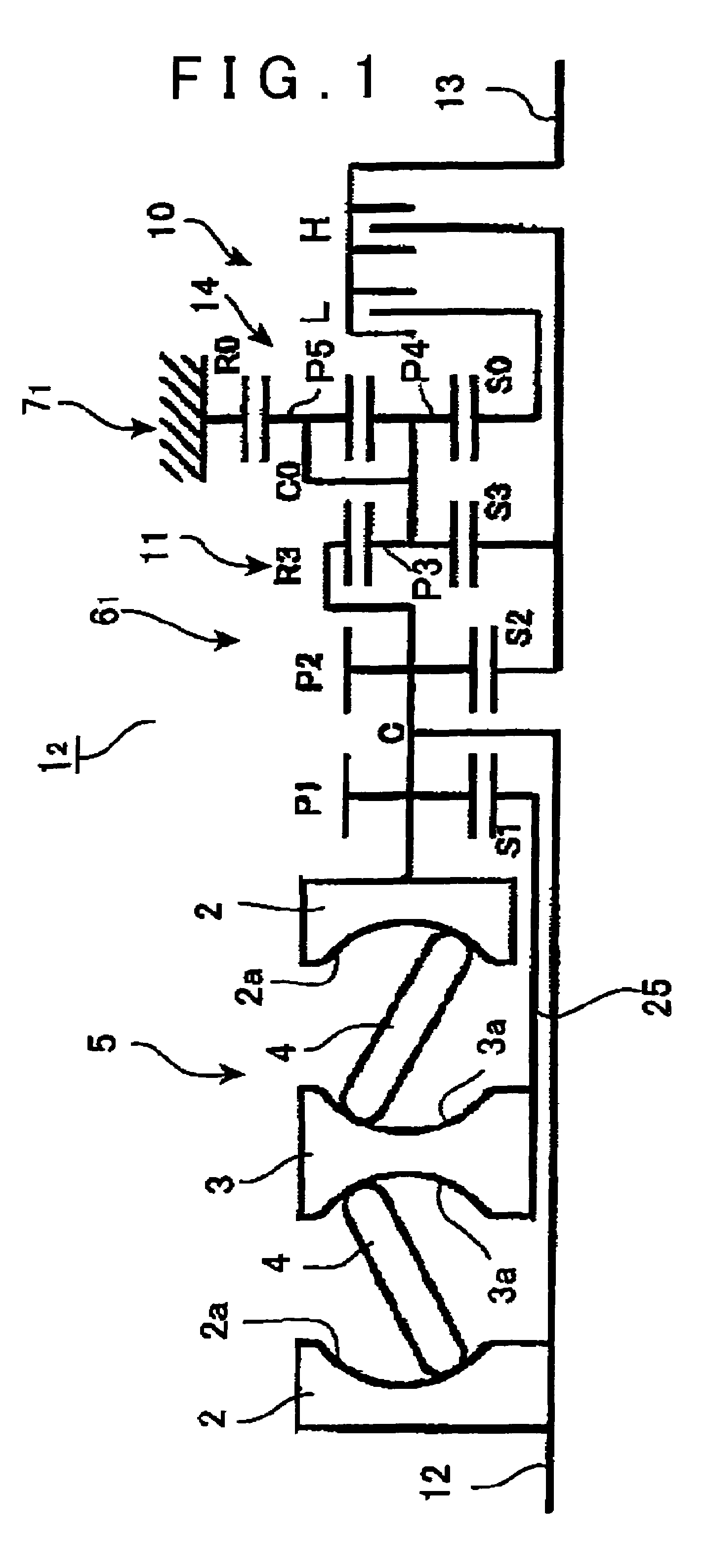
[0008]The present invention provides a continuously variable transmission which overcomes the foregoing problems by providing a simple planetary gear unit for a Low mode. More specifically, the present invention provides a continuously variable transmission which includes a main planetary gear mechanism with a two-step pinion in combination with a simple planetary gear unit. The pinion shaft is relatively short but sufficiently long to support an axial array of pinions. As a result, the bearing which rotatably supports the pinions can be larger in diameter, which increases the length of the bearing service life and reduces bending of the pinion shaft and thus reduces the load fluctuation on the bearing that results from such bending. Further, the pinion weight is lightened such that the load caused by centrifugal force is reduced. The combination of these factors improves the precision with which the pinions are supported and enables that high precision to be maintained over an extended period of time.
[0009]Preferably, a Low mode is established by a simple planetary gear unit, which makes it easier to set the gear ratio for an infinitely variable transmission (IVT). Also, increasing the number of teeth of the pinion of the first carrier of the main planetary gear mechanism makes it possible to maintain the gear strength with a small tooth width and to shorten the axial dimension of the planetary gear mechanism so that the continuously variable transmission can be made more compact.
[0010]Further, the input shaft and the input disc of the toroidal speed change unit are connected to the first carrier, the output disc of the toroidal speed change unit is connected to the first sun gear, and the central portion of the toroidal speed change unit is provided with two heavy shafts, thus resulting in compact and logical connecting relationships.

Problems solved by technology

As a result, the bearing which rotatably supports the pinions can be larger in diameter, which increases the length of the bearing service life and reduces bending of the pinion shaft and thus reduces the load fluctuation on the bearing that results from such bending.

Method used


Image

  • Continuously variable transmission
  • Continuously variable transmission
  • Continuously variable transmission

Examples


Embodiment Construction

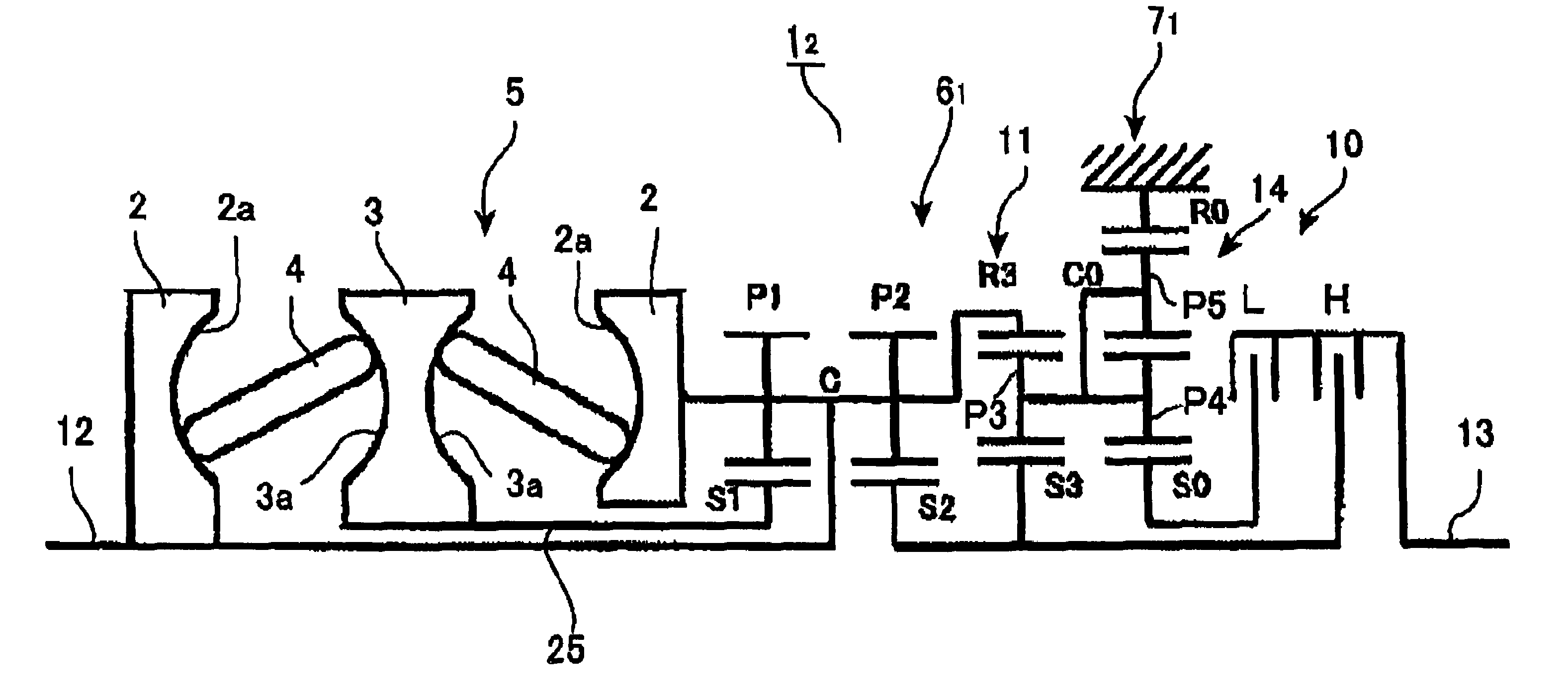
[0026]FIG. 7 shows an embodiment of a continuously variable transmission in which the length of the axial dimension is decreased by using a double pinion planetary gear set for the counter gear mechanism. As shown in FIG. 7, this continuously variable transmission 11 includes a toroidal-type continuously variable speed change unit (CVCU) 5 and a planetary gear mechanism 6, which are similar to those described in connection with the “related art”, and a counter gear mechanism 71 which is a double pinion planetary gear unit. That is, a carrier C0 rotatably supports pinions P4, P5 which are in mesh with each other, while one pinion P4 is in mesh with a sun gear S0 and the other pinion P5 is in mesh with a ring gear R0. The sun gear S0 is connected to the third sun gear (i.e., the Low mode output gear) S3 of the planetary gear mechanism 6, the ring gear R0 is fixed to case 15, and the carrier C0 is coupled to the output shaft 13 via the Low clutch L.

[0027]The continuously variable trans...


PUM


Abstract

Rotation of an input shaft is directly transmitted to a front carrier of a planetary gear mechanism, and rotation, which is speed-changed and reversed by a toroidal-type continuously variable speed change unit, is transmitted to a first sun gear. When a Low clutch is applied, rotation of an output carrier of a simple planetary gear unit is transitted to a counter gear mechanism via a common carrier, and then output at an output shaft. When a High clutch H is applied, rotation of a second sun gear is transmitted to the output shaft. Thus, the pinion shaft is shortened and the service life span of a supporting bearing is increased as compared with a planetary gear mechanism that has a three-step pinion.

Description

BACKGROUND OF THE INVENTION[0001]1. Field of the Invention[0002]The present invention relates to a continuously variable transmission which provides a wider range of input / output speed ratios than does a conventional continuously variable speed-change unit, by combining a toroidal-type continuously variable speed change unit and a planetary gear mechanism with torque circulation.[0003]2. Description of the Related Art[0004]A continuously variable transmission which includes a toroidal-type continuously variable speed change unit and has all of its components arranged on a single axis is disclosed WO Publication WO03 / 100295A1. As shown in FIG. 6(a), this continuously variable transmission 1 includes a toroidal-type continuously variable speed change unit 5, a planetary gear mechanism 6, a counter gear mechanism 7, and a Low / High switching mechanism 10, all of which are arranged on a single axis between an input shaft 12 and an output shaft 13. The toroidal-type continuously variable ...

Claims


Application Information

Patent Timeline
Patent Type & Authority Patents(United States)
IPC IPC(8): F16H37/02
CPCF16H37/086F16H2037/0886
Inventor TSUCHIYA, SAOTOHASEBE, MASAHIROKAI, NORIHIRO
Owner EQUOS RES
Learn More